Inquire: Call 0086-755-23203480, or reach out via the form below/your sales contact to discuss our design, manufacturing, and assembly capabilities.
Quote: Email your PCB files to Sales@pcbsync.com (Preferred for large files) or submit online. We will contact you promptly. Please ensure your email is correct.
Notes: For PCB fabrication, we require PCB design file in Gerber RS-274X format (most preferred), *.PCB/DDB (Protel, inform your program version) format or *.BRD (Eagle) format. For PCB assembly, we require PCB design file in above mentioned format, drilling file and BOM. Click to download BOM template To avoid file missing, please include all files into one folder and compress it into .zip or .rar format.
There’s a sweet spot in PCB material selection that many engineers overlook. While everyone debates between standard Tg 130 and high-performance Tg 170+, the Tg 150 PCB quietly handles the majority of industrial and upgraded consumer applications. After working on hundreds of designs ranging from automotive infotainment to industrial sensors, I’ve come to appreciate why mid-Tg materials deserve more attention than they typically receive.
This guide covers everything you need to know about Tg 150 PCB — when it makes sense, when it doesn’t, and how to specify it correctly for your next project.
What is Tg 150 PCB? Understanding Mid-Tg Materials
The “Tg” in Tg 150 PCB stands for Glass Transition Temperature — the temperature at which your PCB substrate transitions from a rigid, glass-like state to a softer, more flexible condition. At 150°C, the FR4 epoxy resin begins this phase change.
Unlike standard Tg 130-140°C materials (which I’d call “basic”) or high-Tg 170°C+ materials (which are premium), Tg 150 PCB sits squarely in the middle ground. This positioning gives it a unique advantage: better thermal performance than standard materials without the cost and manufacturing complexity of high-Tg substrates.
Here’s how the industry classifies FR4 materials by glass transition temperature:
Classification
Tg Range
Common Designations
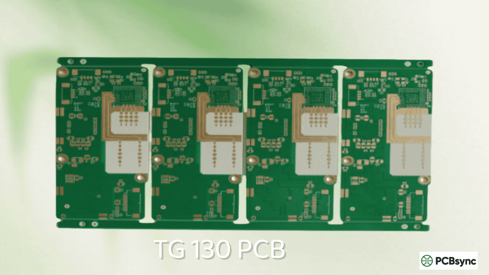
Standard/Low Tg
130-140°C
FR4, Tg 130, Tg 135, Tg 140
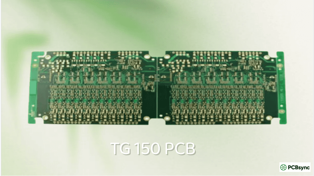
Medium/Mid Tg
150-165°C
Tg 150, Tg 155, Tg 160
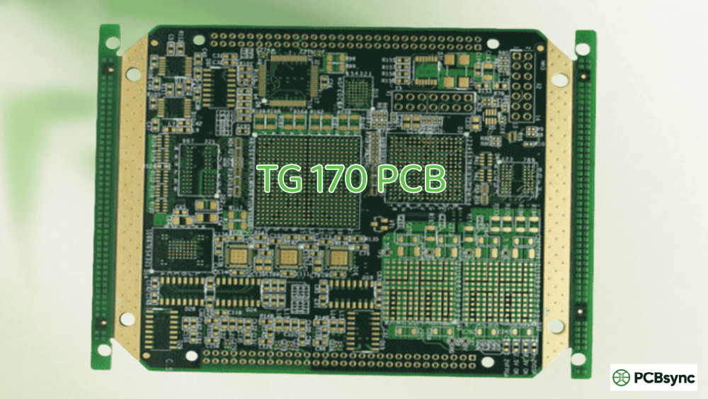
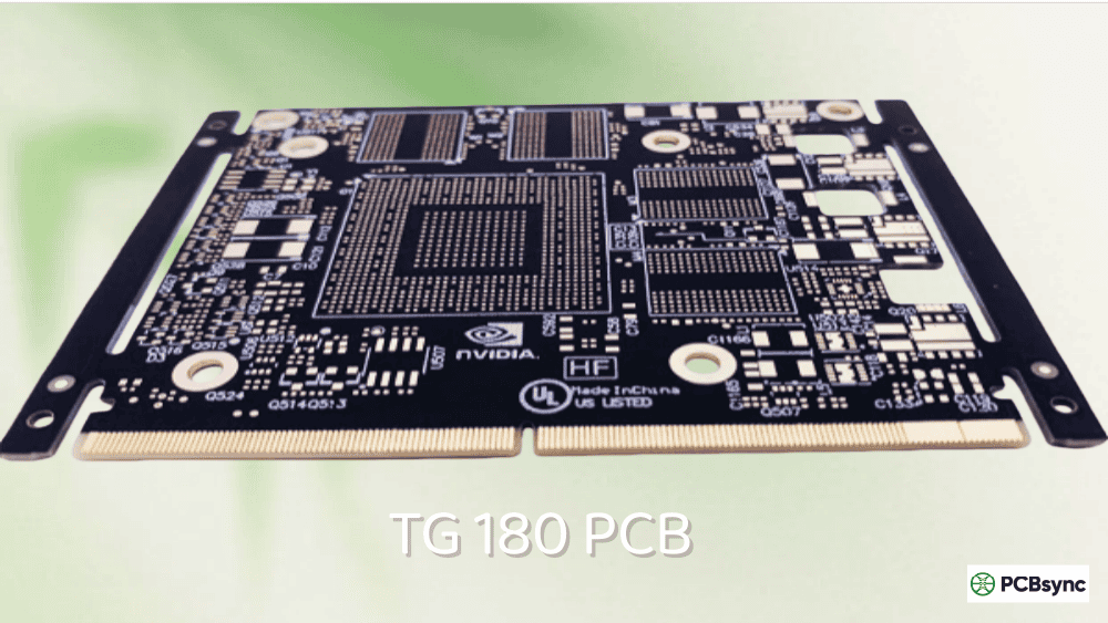
High Tg
170-200°C
Tg 170, Tg 180, Tg 185
One critical point to remember: Tg value ≠ maximum operating temperature. Your Tg 150 PCB should operate at least 25-30°C below its glass transition point for long-term reliability. That means a practical continuous operating limit of around 120-125°C — significantly better than the ~105°C limit of standard Tg 130 material.
Why Tg 150 PCB Exists: The Performance-Cost Balance
Here’s the engineering reality: not every application needs Tg 170+ material, but many applications have outgrown standard Tg 130. The Tg 150 PCB fills this gap perfectly.
The Problem with Standard Tg 130
Standard FR4 works fine for basic consumer electronics, but it struggles with:
Understanding the technical specifications helps you evaluate whether Tg 150 PCB meets your design requirements. These values represent typical ranges across major manufacturers like Shengyi, ITEQ, Isola, and Panasonic.
High-reliability applications with long service life
Lead-Free Soldering Compatibility with Tg 150 PCB
One of the primary reasons engineers specify Tg 150 PCB is lead-free assembly compatibility. Let me explain why this matters.
The Lead-Free Challenge
Lead-free solder alloys (SAC305, SAC387, etc.) require higher reflow temperatures than traditional tin-lead solder:
Solder Type
Peak Reflow Temperature
Duration Above Liquidus
Tin-Lead (Sn63/Pb37)
210-230°C
60-90 seconds
Lead-Free (SAC305)
240-260°C
60-90 seconds
During lead-free reflow, standard Tg 130 material experiences:
Temperature exceeding Tg by 100-130°C
Significant Z-axis expansion
Resin weight loss (1.5-3% per reflow cycle)
Increased risk of delamination
Via barrel cracking potential
How Tg 150 PCB Performs
The Tg 150 PCB handles lead-free soldering better because:
Higher Td value (~320°C): More thermal headroom before decomposition
Lower Z-axis CTE: Less expansion during reflow peaks
Better resin stability: Less weight loss per thermal cycle
Improved T260/T288 performance: Longer time to delamination
For most lead-free applications with single or double-sided reflow, Tg 150 PCB provides adequate margin. However, if your process requires multiple reflow cycles (rework, sequential assembly), consider Tg 170+ for additional safety.
The Tg 150 PCB finds its home in applications that have outgrown standard materials but don’t justify high-Tg pricing. Here’s where I see it used most often.
Automotive Electronics (Interior Systems)
Modern vehicles contain dozens of electronic control units, most of which don’t sit in the engine compartment. Interior automotive applications are perfect candidates for Tg 150 PCB:
Infotainment systems and navigation
Instrument clusters and displays
Climate control modules
Body control modules
Door and seat electronics
Lighting controllers
These systems experience ambient temperatures up to 85°C with occasional spikes higher. Tg 150 provides comfortable margin while keeping costs reasonable for high-volume automotive production.
UL Product iQ Database: Certification verification for laminates
Frequently Asked Questions About Tg 150 PCB
Is Tg 150 PCB suitable for lead-free soldering?
Yes, Tg 150 PCB handles standard lead-free soldering processes well. The higher decomposition temperature (Td ~320°C) and improved thermal stability provide adequate margin for reflow temperatures of 240-260°C. For single or double-sided reflow, Tg 150 is a reliable choice. However, if your process requires multiple reflow cycles or extensive rework, consider upgrading to Tg 170+ for additional safety margin.
What’s the maximum operating temperature for Tg 150 PCB?
The practical maximum continuous operating temperature is approximately 120-125°C. The general rule is to maintain operating temperature at least 25-30°C below the Tg value. Brief temperature excursions above this threshold during events like soldering won’t cause immediate damage, but sustained operation near Tg accelerates material degradation and reduces reliability.
When should I upgrade from Tg 130 to Tg 150?
Consider upgrading to Tg 150 PCB when any of these conditions apply: operating temperatures exceed 85°C regularly, you’re using lead-free assembly processes, your design has 6+ layers, the product requires improved long-term reliability, or thermal cycling is part of the operating environment. The 5-10% cost premium typically pays for itself in improved yield and field reliability.
Can Tg 150 PCB replace Tg 170 in my design?
It depends on your specific requirements. Tg 150 PCB can replace Tg 170 when: operating temperatures stay below 120°C, layer count is 10 or fewer, you don’t need multiple reflow cycles, and the application isn’t aerospace/military grade. However, if you’re working on automotive under-hood electronics, high-layer-count boards, or applications requiring maximum thermal margin, stick with Tg 170+.
How do I specify Tg 150 PCB when ordering?
When ordering, specify: “FR4, Tg ≥150°C (DSC)” in your fabrication notes. Include the specific material manufacturer and designation if you have a preference (e.g., “Shengyi S1000H or equivalent”). Request the Certificate of Compliance showing actual Tg measurement. Also specify any halogen-free requirements if applicable, as both halogenated and halogen-free Tg 150 options exist.
Conclusion: Making the Right Tg 150 PCB Decision
The Tg 150 PCB represents the practical middle ground in PCB material selection. It’s not the cheapest option, and it’s not the highest performance — but for a huge range of industrial, automotive, and premium consumer applications, it hits the sweet spot.
Here’s my summary guidance:
Use Tg 150 PCB when:
You’ve identified thermal limitations with standard Tg 130
Lead-free assembly is required with reasonable thermal margin
Cost matters but so does reliability
The application is industrial-grade or automotive interior
Layer count is moderate (4-10 layers)
Don’t use Tg 150 PCB when:
Basic consumer electronics with no thermal concerns (use Tg 130)
Extreme environment applications (use Tg 170+)
Very high layer counts above 12 layers (use Tg 170+)
Multiple reflow cycles are required (use Tg 170+)
The key is matching material capability to actual application requirements. Over-specifying wastes money; under-specifying risks field failures. Understanding where Tg 150 PCB fits in the spectrum helps you make that match correctly.
When in doubt, discuss your specific application with your PCB fabricator. Good manufacturers have extensive experience with all Tg levels and can provide guidance based on your design parameters and operating conditions.
This guide reflects practical engineering experience with PCB material selection. Specific material properties vary by manufacturer — always verify values against your laminate supplier’s current datasheet.
Inquire: Call 0086-755-23203480, or reach out via the form below/your sales contact to discuss our design, manufacturing, and assembly capabilities.
Quote: Email your PCB files to Sales@pcbsync.com (Preferred for large files) or submit online. We will contact you promptly. Please ensure your email is correct.
Notes: For PCB fabrication, we require PCB design file in Gerber RS-274X format (most preferred), *.PCB/DDB (Protel, inform your program version) format or *.BRD (Eagle) format. For PCB assembly, we require PCB design file in above mentioned format, drilling file and BOM. Click to download BOM template To avoid file missing, please include all files into one folder and compress it into .zip or .rar format.


