Inquire: Call 0086-755-23203480, or reach out via the form below/your sales contact to discuss our design, manufacturing, and assembly capabilities.
Quote: Email your PCB files to Sales@pcbsync.com (Preferred for large files) or submit online. We will contact you promptly. Please ensure your email is correct.
Notes: For PCB fabrication, we require PCB design file in Gerber RS-274X format (most preferred), *.PCB/DDB (Protel, inform your program version) format or *.BRD (Eagle) format. For PCB assembly, we require PCB design file in above mentioned format, drilling file and BOM. Click to download BOM template To avoid file missing, please include all files into one folder and compress it into .zip or .rar format.
After 12 years of designing circuit boards across consumer electronics, industrial controls, and telecommunications equipment, I’ve found that material selection remains one of the most overlooked aspects of PCB design. Many engineers default to whatever material their manufacturer suggests without understanding the implications. This guide breaks down everything you need to know about Tg 130 PCB — the industry’s workhorse material that balances cost, performance, and manufacturability.
What is Tg 130 PCB? Understanding Glass Transition Temperature
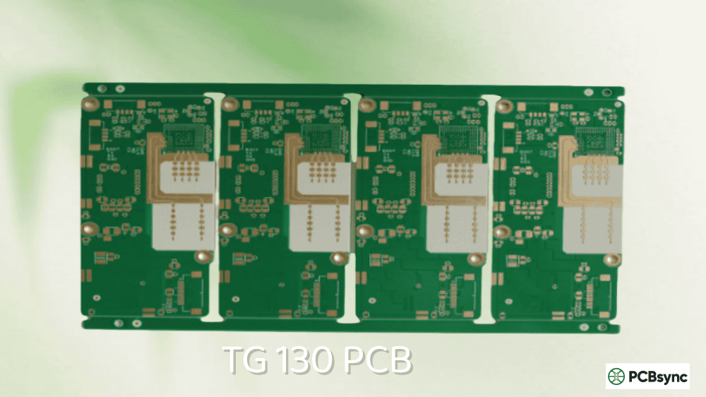
The “Tg” in Tg 130 PCB stands for Glass Transition Temperature — the point where your PCB substrate shifts from a rigid, glass-like state to a softer, more flexible condition. At 130°C, the FR4 material begins this transition, though it won’t melt or burn at this temperature.
Think of it like this: your PCB substrate behaves predictably below its Tg value. Push it above that threshold, and things get problematic — dimensional stability suffers, mechanical properties degrade, and your carefully designed traces may not perform as expected.
The Tg 130 PCB classification represents the standard or “low Tg” category in the industry hierarchy:
Tg Classification
Temperature Range
Typical Applications
Standard/Low Tg
130-140°C
Consumer electronics, general-purpose
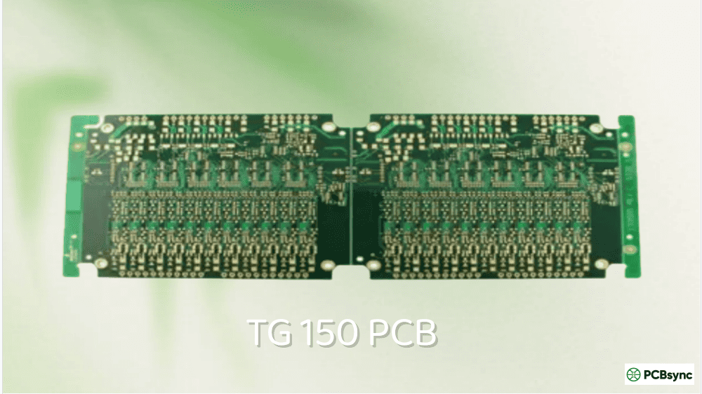
Medium Tg
150-160°C
Industrial, automotive interior
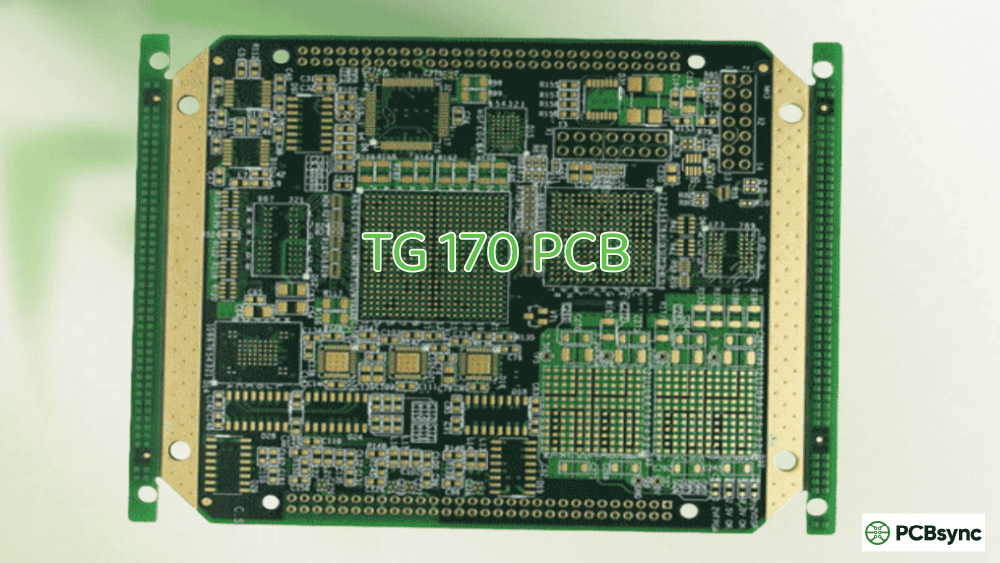
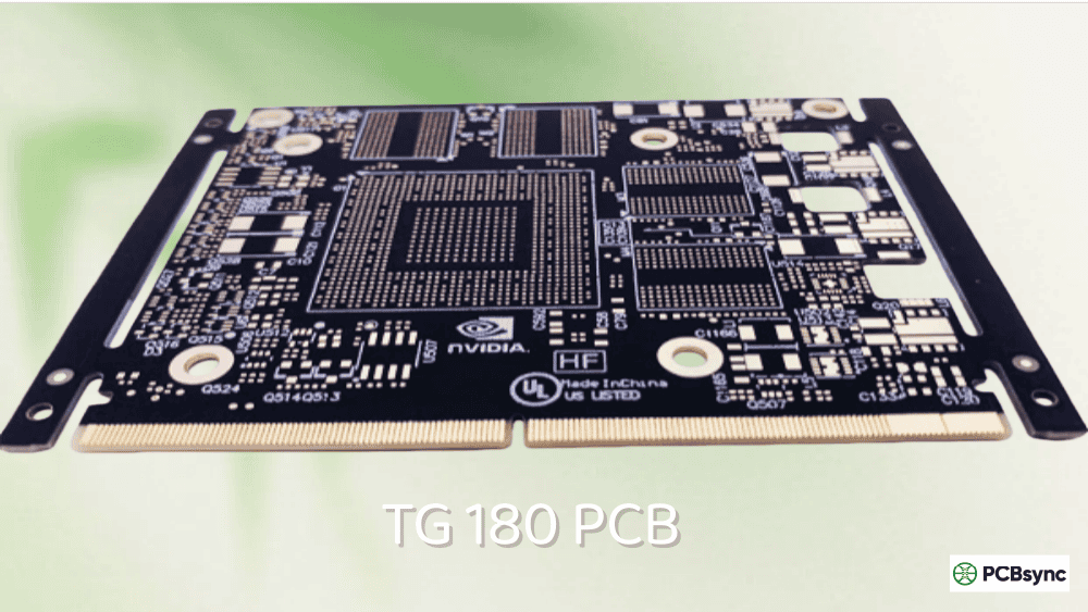
High Tg
170°C+
Automotive under-hood, aerospace, military
One critical point that trips up many designers: Tg value ≠ operating temperature. You should always operate your Tg 130 PCB at least 25°C below the glass transition point — that means keeping your board temperature under 105°C for reliable long-term performance.
FR4 Tg 130 is a composite material engineered for specific electrical and mechanical properties. Understanding what’s inside helps you make better design decisions.
Core Components
Woven Fiberglass Cloth: The structural backbone of FR4. E-glass fibers woven in specific patterns provide mechanical strength and dimensional stability. The weave style (1080, 2116, 7628, etc.) affects both electrical performance and cost.
Epoxy Resin System: Halogenated or halogen-free epoxy resin binds the glass fibers together and provides the flame-retardant properties that give FR4 its name (Flame Retardant Type 4). The resin formulation determines the Tg value.
Copper Cladding: Electrodeposited copper foil bonded to the laminate surface, typically available in weights from 0.5 oz/ft² to 3 oz/ft² for standard applications. This copper gets etched to form your circuit traces.
FR4 Tg 130 Technical Specifications
Based on common manufacturer datasheets, here are typical specifications for FR4 Tg 130 material:
These numbers matter when you’re calculating impedance, estimating thermal performance, or ensuring your design meets regulatory requirements.
Why Choose Tg 130 PCB? Key Benefits
Cost-Effectiveness
Let me be direct: Tg 130 PCB is the cheapest rigid PCB material you can specify that still meets professional standards. The price differential is significant — Tg 150 material typically costs 5-10% more, while Tg 170+ can add 15-25% to your laminate costs.
For high-volume production where you’re ordering thousands of boards, this translates to substantial savings. If your application doesn’t require higher thermal performance, specifying Tg 170 is literally throwing money away.
Manufacturing Familiarity
Every PCB fabricator on the planet has extensive experience with FR4 Tg 130. This translates to:
Shorter lead times (material is always in stock)
Fewer manufacturing defects (established process parameters)
More competitive pricing (multiple suppliers)
Better technical support (fab houses know this material inside out)
When you specify exotic materials, you’re introducing risk. Tg 130 is the safe choice from a manufacturing perspective.
Adequate Thermal Performance for Most Applications
Here’s a reality check: most consumer electronics never see sustained temperatures above 85°C during operation. Smartphones, tablets, home automation devices, office equipment — these products operate well within the Tg 130 safety margin.
Even accounting for localized hot spots around power components, proper thermal management (heat sinks, thermal vias, copper pours) keeps temperatures manageable without requiring exotic substrates.
Excellent Electrical Properties
For applications up to approximately 1 GHz, FR4 Tg 130 provides stable dielectric properties. The material maintains consistent impedance characteristics, adequate insulation resistance, and acceptable signal integrity for most digital and low-frequency analog designs.
Mechanical Durability
The flexural strength of FR4 Tg 130 (415-510 MPa) handles the mechanical stresses of component mounting, assembly processes, and normal product handling. For standard rigid PCB applications, this durability is more than sufficient.
Tg 130 PCB vs Higher Tg Materials: When to Upgrade
This is where many engineers get confused. Let me give you practical guidance on when standard Tg 130 isn’t enough.
Lead-Free Assembly Concerns: Lead-free solder reflow profiles peak at 240-260°C. While this is brief exposure, multiple reflow cycles (double-sided assembly, rework) can stress Tg 130 material. For boards requiring several thermal excursions, Tg 150 or higher provides better margin.
High Layer Count Designs: Each lamination cycle subjects the board to elevated temperatures. For designs exceeding 10-12 layers, the cumulative thermal stress during PCB manufacturing makes higher Tg material advisable.
Elevated Operating Environments: If your product operates in environments exceeding 85°C continuously — automotive under-hood, industrial ovens, outdoor power equipment — upgrade your material selection.
Dense Power Electronics: High-power density designs with significant heat generation near the board require better thermal stability. Switching power supplies, motor drivers, and LED drivers with tight thermal budgets may need higher Tg.
Since Tg 130 has lower thermal headroom, proper thermal design becomes more important:
Thermal Via Arrays: Place arrays of vias under hot components to conduct heat to inner layers or the opposite side of the board. Use 0.3mm diameter vias spaced 1.0-1.5mm apart for effective heat spreading.
Copper Pour Utilization: Maximize copper area on unused board real estate. Connected copper pours act as heat spreaders, reducing localized hot spots.
Component Placement: Position heat-generating components away from temperature-sensitive parts. Consider airflow patterns if your enclosure uses forced or natural convection.
Adequate Spacing: Leave sufficient clearance around high-power components for heat dissipation.
Layer Stackup Recommendations
For Tg 130 material, standard stackups work well up to 10 layers:
Immersion Tin: Good solderability, limited shelf life
Hard Gold: Required for edge connectors and gold fingers
Surface finish selection doesn’t affect Tg value — choose based on your assembly requirements and shelf life needs.
Tg 130 PCB Manufacturing Process
Understanding how Tg 130 PCB boards are manufactured helps you communicate better with your fabricator and avoid common pitfalls.
Lamination Process
The lamination process bonds copper foil, prepreg (resin-impregnated fiberglass), and core materials under controlled temperature and pressure. For Tg 130 material, typical lamination parameters are:
Temperature: 180-200°C
Pressure: 5-10 MPa (725-1450 psi)
Cycle Time: 60-120 minutes depending on layer count
The lamination temperature is well above the Tg value, which allows the resin to flow and bond layers together. After curing, the material returns to its rigid state with enhanced cross-linking.
Drilling Considerations
FR4 Tg 130 machines well with standard tungsten carbide drill bits. Recommended parameters for standard through-holes:
Hole Size
Spindle Speed
Feed Rate
Notes
0.2-0.3mm
80,000-100,000 RPM
2.0-2.5 m/min
Requires backup entry material
0.3-0.5mm
60,000-80,000 RPM
2.5-3.0 m/min
Standard production hole
0.5-1.0mm
40,000-60,000 RPM
3.0-4.0 m/min
No special requirements
>1.0mm
20,000-40,000 RPM
4.0-5.0 m/min
Consider step drilling
Plating and Etching
Standard electroless and electrolytic copper plating processes work well with Tg 130 material. The epoxy surface accepts chemical treatment for copper adhesion without special preparation. Alkaline and acidic etching solutions are both compatible.
Common Applications for Tg 130 PCB
Consumer Electronics
The largest market for Tg 130 PCB material. Smartphones, tablets, laptops, gaming consoles, streaming devices, smart speakers — all these products typically use standard FR4 Tg 130 material. The operating temperatures are moderate, volumes are high, and cost pressure is intense.
Telecommunications Equipment
Routers, modems, network switches, and access points commonly use Tg 130 material. For standard data rates and ambient temperature operation, this material provides adequate performance at competitive cost.
Industrial Controls
PLCs, sensor interfaces, motor controllers for moderate environments, and process control equipment frequently specify Tg 130. For elevated temperature industrial applications, designers often upgrade to Tg 150 or higher.
Medical Devices
Non-critical medical devices and diagnostic equipment often use Tg 130 material. However, implantable devices and equipment requiring autoclaving (steam sterilization at 121°C+) need higher Tg materials.
Automotive Interior Electronics
Infotainment systems, instrument clusters, climate controls, and interior lighting modules typically use Tg 130 or Tg 150 material. Under-hood electronics require Tg 170+ due to engine compartment temperatures.
Environmental Considerations and Storage
Moisture Sensitivity
FR4 Tg 130 has relatively low moisture absorption (≤0.10%), but exposed laminate can absorb atmospheric moisture over time. This matters because:
Absorbed moisture expands rapidly during soldering, causing delamination or “popcorning”
Moisture affects dielectric properties, especially at higher frequencies
Long-term moisture exposure can degrade copper-to-laminate adhesion
Storage recommendations:
Store laminates in sealed moisture barrier bags with desiccant
Maintain storage environment at <30°C and <60% relative humidity
Track shelf life — most laminates have 6-12 month storage limits before baking
Bake boards at 120-150°C for 2-4 hours if moisture contamination is suspected
Pre-Assembly Baking
If your Tg 130 PCBs have been stored improperly or for extended periods, a pre-assembly bake removes absorbed moisture:
Board Thickness
Bake Temperature
Bake Duration
<1.0mm
105-120°C
2-4 hours
1.0-2.0mm
105-120°C
4-6 hours
>2.0mm
105-120°C
6-8 hours
After baking, use boards within 8 hours or store in dry nitrogen environment.
RoHS and REACH Compliance
Modern Tg 130 PCB materials are available in both halogenated (traditional) and halogen-free formulations. For products sold in the EU or other regions with strict environmental regulations, specify halogen-free variants. These maintain the same Tg value while eliminating brominated flame retardants.
End-of-Life Considerations
FR4 composite materials are challenging to recycle due to the mixed material composition. However:
Copper can be recovered through mechanical separation or chemical processes
Glass fibers can be recycled for use in lower-grade applications
Some advanced recycling processes can recover epoxy resin components
When selecting Tg 130 material, consider your product’s full lifecycle and any take-back or recycling obligations.
Testing Methods for Tg 130 PCB Material
Understanding how manufacturers verify Tg values helps you evaluate supplier quality claims.
Differential Scanning Calorimetry (DSC)
The most common method for Tg measurement. DSC tracks heat flow into a sample as temperature increases, detecting the thermal transition point. This technique is sensitive and provides clear Tg identification.
Thermomechanical Analysis (TMA)
TMA measures dimensional changes as temperature increases. The sharp increase in thermal expansion rate at Tg makes this technique effective for Tg determination.
Dynamic Mechanical Analysis (DMA)
DMA measures the material’s mechanical response to oscillating stress at various temperatures. It’s the most sensitive technique for detecting glass transition, particularly useful for precise Tg characterization.
Cost Factors for Tg 130 PCB Manufacturing
Several factors influence the final cost of your Tg 130 PCB:
IPC-2152: Standard for determining current carrying capacity in PCB design
Frequently Asked Questions About Tg 130 PCB
Is Tg 130 PCB suitable for lead-free soldering?
Yes, with caveats. Tg 130 PCB can handle lead-free soldering profiles (peak 240-260°C) for single-sided or simple double-sided assemblies. However, for boards requiring multiple reflow cycles, rework, or high-reliability applications, Tg 150 or higher provides better margin. The brief exposure during soldering is within tolerance, but accumulated thermal stress from multiple cycles can cause issues.
What’s the maximum operating temperature for Tg 130 PCB?
Practical maximum is around 105°C for long-term reliable operation. The general rule is to stay 25°C below the Tg value. Brief temperature excursions above this threshold won’t immediately damage the board, but sustained operation near Tg accelerates aging and can cause dimensional stability problems.
Can I use Tg 130 PCB for automotive applications?
It depends on the specific application. Interior electronics (infotainment, instrument clusters, interior lighting) typically use Tg 130 or Tg 150 successfully. Under-hood applications require Tg 170+ due to elevated ambient temperatures. Always check your specific thermal requirements against worst-case operating conditions.
How many layers can I reliably manufacture with Tg 130 material?
Standard practice supports up to 10-12 layers with Tg 130 material. Beyond this, the cumulative thermal stress from multiple lamination cycles makes higher Tg material advisable. For 14+ layer designs, most engineers specify Tg 150 or higher to ensure manufacturing stability.
What’s the difference between FR4 Tg 130 and standard FR4?
They’re often the same thing. “Standard FR4” typically refers to Tg 130-140°C material. The Tg 130 designation simply makes the glass transition temperature explicit. When you order “FR4” without specifying Tg, most fabricators will supply Tg 130-140 material. Always confirm with your manufacturer if Tg value is critical to your application.
Conclusion: Making the Right Material Choice
Tg 130 PCB remains the backbone of the electronics industry for good reason. It delivers adequate thermal performance for the vast majority of applications at the lowest cost point. Before automatically specifying higher Tg materials, evaluate your actual thermal requirements:
What’s the maximum sustained operating temperature?
How many thermal cycles will the board experience during manufacturing?
What’s your cost sensitivity for the production volume?
Does your application truly need higher thermal performance?
For most consumer, commercial, and general industrial applications, Tg 130 PCB is the right choice. Save the higher Tg materials for applications that genuinely require them — your procurement team and your customers’ wallets will thank you.
The key is matching material capability to application requirements. Overspecifying wastes money; underspecifying risks reliability. Understanding Tg 130 PCB capabilities helps you make that match correctly.
This guide reflects practical experience in PCB design and manufacturing. Material specifications vary by manufacturer — always verify specific values with your laminate supplier’s datasheet for your production material.
Inquire: Call 0086-755-23203480, or reach out via the form below/your sales contact to discuss our design, manufacturing, and assembly capabilities.
Quote: Email your PCB files to Sales@pcbsync.com (Preferred for large files) or submit online. We will contact you promptly. Please ensure your email is correct.
Notes: For PCB fabrication, we require PCB design file in Gerber RS-274X format (most preferred), *.PCB/DDB (Protel, inform your program version) format or *.BRD (Eagle) format. For PCB assembly, we require PCB design file in above mentioned format, drilling file and BOM. Click to download BOM template To avoid file missing, please include all files into one folder and compress it into .zip or .rar format.


