Inquire: Call 0086-755-23203480, or reach out via the form below/your sales contact to discuss our design, manufacturing, and assembly capabilities.
Quote: Email your PCB files to Sales@pcbsync.com (Preferred for large files) or submit online. We will contact you promptly. Please ensure your email is correct.
Notes: For PCB fabrication, we require PCB design file in Gerber RS-274X format (most preferred), *.PCB/DDB (Protel, inform your program version) format or *.BRD (Eagle) format. For PCB assembly, we require PCB design file in above mentioned format, drilling file and BOM. Click to download BOM template To avoid file missing, please include all files into one folder and compress it into .zip or .rar format.
Generate gerber file from Altium(DXP/.PCB.PCBDOC): A Complete Engineering Guide
Generating Gerber files from Altium Designer is a critical step in transitioning your PCB design from the digital workspace to physical fabrication. Whether you’re working with legacy DXP formats or modern .PcbDoc files, understanding the proper export workflow ensures your manufacturer receives accurate, fabrication-ready data. This comprehensive guide walks you through the complete process, from pre-export preparation to final file packaging.
Understanding Gerber Files and Their Role in PCB Fabrication
Gerber files serve as the universal language between PCB designers and manufacturers. These industry-standard files contain all the graphical information required to fabricate each layer of your printed circuit board. When you generate Gerber files from Altium, you’re essentially creating a precise blueprint that photoplotters and CNC machines can interpret directly.
The RS-274X format (Extended Gerber) has become the de facto standard, embedding aperture information directly within the file. This eliminates the need for separate aperture lists and reduces the potential for misinterpretation during manufacturing. Altium Designer fully supports this format, making the export process straightforward once you understand the correct parameter settings.
Pre-Export Preparation: Setting Up Your PCB File
Before generating Gerber output, proper preparation of your PCB file significantly reduces the likelihood of fabrication errors. While most designers can proceed directly to export, certain preprocessing steps prove valuable for complex designs.
First, verify your board outline definition. The mechanical layer (typically Mechanical 1 or 2) should contain a closed polygon representing your PCB boundary. Manufacturers rely on this outline to determine cutting paths and panel placement.
Additionally, consider these preprocessing elements for production-ready designs:
Breakaway rails and panelization marks for automated assembly
Stamp holes or mouse bites for panel separation
Fiducial markers for pick-and-place alignment
Mounting holes with appropriate clearances
Dimension annotations on designated mechanical layers
Origin point configuration (Design → Board Options)
Setting the origin point correctly ensures all coordinates reference a consistent location, preventing layer misalignment during fabrication.
Step-by-Step Gerber File Generation Process
Accessing the Gerber Output Configuration
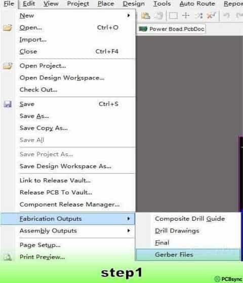
Navigate to File → Fabrication Outputs → Gerber Files from your PCB editor. This opens the Gerber Setup dialog where you’ll configure all export parameters. Altium Designer provides granular control over the output format, layer selection, and coordinate handling.
Configuring General Settings
The General tab establishes fundamental format parameters that affect how coordinates and dimensions are encoded within your Gerber files.
Set the Units parameter to “Inches” for maximum compatibility with North American and Asian fabricators. While metric options exist, inch-based formats remain the industry default for Gerber data exchange.
Configure the Format field to “2:5” precision. This specification allocates two digits for integer positions and five digits for decimal places, providing resolution to 0.00001 inches (0.254 micrometers). Such precision adequately represents even the finest trace geometries in modern high-density designs.
Layer Selection and Configuration
The Layers tab determines which PCB layers Altium exports to individual Gerber files. Proper configuration here prevents missing layers or unnecessary file generation.
Select “Used On” from the Plot Layers dropdown. This intelligent option automatically identifies and exports only those layers containing actual design data, eliminating empty files from your output package.
Under Mirror Layers, choose “All Off” unless your manufacturer specifically requests mirrored artwork. Modern fabrication processes handle layer orientation programmatically, making manual mirroring unnecessary and potentially confusing.
Enable the “Include unconnected mid-layer pads” checkbox. This ensures thermal relief pads and test points on internal layers export correctly, even when they lack direct trace connections.
Critically, uncheck all options under “Mechanical Layers to Add to All Plots.” Adding mechanical layer data to copper layers creates fabrication ambiguity and may result in unwanted copper features on your finished boards.
Drill Drawing Configuration
Access the Drill Drawing tab and disable all checkboxes. The drill drawing feature generates legacy-format graphical representations of hole locations intended for manual verification. Modern manufacturers extract drill information from NC drill files rather than graphical overlays.
Set Drill Drawing Symbols to “Graphic Symbols” for compatibility, though this setting becomes irrelevant when drill drawings are disabled.
Aperture Format Selection
The Apertures tab controls how tool definitions are communicated within your Gerber files. Select “RS274X” to embed aperture information directly within each Gerber file. This self-contained approach eliminates dependency on external aperture lists and represents current industry best practice.
Avoid the older RS274D format, which requires separate aperture files and introduces version-matching complications during manufacturing.
Advanced Output Parameters
The Advanced tab contains settings that affect file organization and coordinate encoding.
Configure Batch Mode to “Separate file per layer” to generate individual Gerber files for each PCB layer. This organization simplifies manufacturer review and selective layer modification if required.
Set Leading/Trailing Zeroes to “Suppress leading zeroes.” This option removes unnecessary zero padding from coordinate values, reducing file size without sacrificing precision.
Select “Reference to relative origin” under Position on Film. This anchors all coordinates to your defined board origin rather than absolute CAD coordinates, ensuring consistent layer registration.
Choose “Unsorted” for Plotter Type to maintain optimal file compatibility across different CAM systems.
Click OK to generate your Gerber files. Altium automatically loads the output into its integrated CAM viewer, enabling immediate visual verification of all layers.
Generating NC Drill Files
Gerber files define copper patterns and solder masks, but hole information requires separate NC drill files in Excellon format. Without proper drill data, your manufacturer cannot produce the via holes and component mounting holes your design requires.
Access the drill file generator via File → Fabrication Outputs → NC Drill Files from your PCB view.
Configure the following parameters:
Units: Inches (matching your Gerber configuration)
Format: 2:5 (consistent precision with Gerber data)
Leading/Trailing Zeroes: Suppress leading zeroes
Coordinate Positions: Reference to relative origin
Click OK to initiate generation. Altium presents Import Drill Data and Import Mill/Route Data dialogs—accept the defaults for both to proceed with standard drilling output.
Packaging and Verifying Your Output Files
Altium Designer automatically saves all generated fabrication files to your project’s output folder. Before submission to manufacturing, package these files appropriately and perform final verification.
Compress all Gerber (.gbr, .gtl, .gbl, etc.) and NC drill (.drl, .txt) files into a single ZIP archive. This consolidated package simplifies file transfer and ensures manufacturers receive complete fabrication data.
Review the generated files in Altium’s CAM viewer or a third-party Gerber viewer. Verify that all layers appear in positive mode (copper where intended), layer alignment matches your design intent, and drill holes correspond to your via and pad locations.
Common Export Issues and Solutions
Layer misalignment typically results from inconsistent origin settings between Gerber and drill file generation. Always use “Reference to relative origin” for both outputs.
Missing internal layers often occur when the “Used On” plot layer option isn’t selected. Verify your layer count matches design requirements.
Oversized file generation may indicate incorrect format precision or embedded preview data. The 2:5 format provides sufficient resolution without excessive file bloat.
Conclusion
Successfully generating Gerber files from Altium Designer requires attention to format settings, layer configuration, and coordinate handling. By following the parameter recommendations outlined above—RS-274X format, 2:5 precision, suppressed leading zeroes, and relative origin referencing—you’ll produce fabrication-ready output compatible with virtually any PCB manufacturer. Always verify your generated files before submission, and maintain consistent settings between Gerber and NC drill generation to ensure proper layer registration during fabrication.
Inquire: Call 0086-755-23203480, or reach out via the form below/your sales contact to discuss our design, manufacturing, and assembly capabilities.
Quote: Email your PCB files to Sales@pcbsync.com (Preferred for large files) or submit online. We will contact you promptly. Please ensure your email is correct.
Notes: For PCB fabrication, we require PCB design file in Gerber RS-274X format (most preferred), *.PCB/DDB (Protel, inform your program version) format or *.BRD (Eagle) format. For PCB assembly, we require PCB design file in above mentioned format, drilling file and BOM. Click to download BOM template To avoid file missing, please include all files into one folder and compress it into .zip or .rar format.


