Inquire: Call 0086-755-23203480, or reach out via the form below/your sales contact to discuss our design, manufacturing, and assembly capabilities.
Quote: Email your PCB files to Sales@pcbsync.com (Preferred for large files) or submit online. We will contact you promptly. Please ensure your email is correct.
Notes: For PCB fabrication, we require PCB design file in Gerber RS-274X format (most preferred), *.PCB/DDB (Protel, inform your program version) format or *.BRD (Eagle) format. For PCB assembly, we require PCB design file in above mentioned format, drilling file and BOM. Click to download BOM template To avoid file missing, please include all files into one folder and compress it into .zip or .rar format.
How to Generate Gerber File from AutoCAD: A Complete Engineering Guide
Generating Gerber files from AutoCAD is an essential skill for PCB designers who prefer working within the AutoCAD environment. While AutoCAD excels at precision drafting and mechanical design, it lacks native Gerber export capabilities, requiring engineers to utilize specialized plugins for PCB manufacturing preparation. This comprehensive guide walks you through the entire process of converting your AutoCAD designs into industry-standard Gerber format.
Understanding Gerber Files and Their Importance in PCB Manufacturing
Before diving into the conversion process, engineers should understand why Gerber files matter. The Gerber format (RS-274X) serves as the universal language between PCB designers and manufacturers. Every fabrication house worldwide accepts Gerber files because they contain precise layer-by-layer information about copper traces, solder masks, silkscreen patterns, and drill locations.
When you design PCB layouts in AutoCAD, your drawings exist as DWG or DXF files containing geometric entities. However, PCB manufacturers cannot directly interpret these formats for photolithography processes. Gerber files bridge this gap by encoding your design data into a format that directly controls the laser plotters and imaging equipment used in PCB production.
Prerequisites: Installing the EasyGerb Plugin
AutoCAD requires a third-party plugin called EasyGerb to enable Gerber file generation. This plugin integrates seamlessly into the AutoCAD environment and provides all necessary tools for converting your PCB designs into manufacturing-ready Gerber output.
System Requirements and Compatibility
EasyGerb supports multiple AutoCAD versions, so you must download the version corresponding to your installed AutoCAD release. The plugin works with AutoCAD 2010 through the latest releases, ensuring broad compatibility across engineering workstations. Before installation, verify your AutoCAD version by typing “ABOUT” at the command prompt.
Loading EasyGerb into AutoCAD
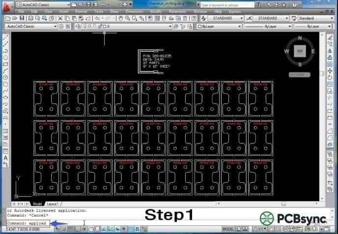
The initial loading process requires administrative access and follows these technical steps. First, launch AutoCAD and access the application loader by entering the “_APPLOAD” command at the command prompt. This opens the Load/Unload Applications dialog box where you can browse to your EasyGerb installation directory.
Navigate to the folder containing the EasyGerb ARX file that matches your AutoCAD version. Select the appropriate file and click “Load” to integrate the plugin into your current AutoCAD session. Upon successful loading, you will see a confirmation message in the command line indicating that EasyGerb has been initialized.
One significant advantage of the EasyGerb plugin is its automatic loading capability. After the initial manual load, EasyGerb configures itself to load automatically whenever you launch AutoCAD, eliminating the need to repeat this process for future sessions.
Step-by-Step Gerber Generation Process
With EasyGerb successfully loaded, you can now convert your AutoCAD PCB designs into Gerber format. The following procedure ensures accurate conversion while maintaining design integrity.
Step 1: Launching the EasyGerb Interface
Access the EasyGerb conversion tool by typing “EasyGerb” at the AutoCAD command prompt and pressing Enter. This command launches the main EasyGerb dialog box, which provides comprehensive control over the conversion parameters and output settings.
Step 2: Configuring Default Settings
The EasyGerb dialog presents several configuration options that directly affect your Gerber output quality. Engineers should carefully review the default settings before proceeding with conversion, as incorrect parameters can result in manufacturing defects or rejected files.
Key configuration parameters include:
Units Configuration: Ensure your units match the design intent. EasyGerb supports both metric (millimeters) and imperial (inches) measurements. Mismatched units represent one of the most common errors in Gerber generation.
Aperture Settings: Define the aperture list that corresponds to your trace widths and pad geometries. EasyGerb can automatically generate apertures based on your drawing entities, though manual definition provides greater control.
Format Specification: Set the coordinate format (typically 2.4 or 2.5 for inches, 3.3 or 4.4 for millimeters) to ensure adequate precision for your design requirements.
Zero Suppression: Configure leading or trailing zero suppression according to your manufacturer’s specifications. Most modern fabricators accept either format, but consistency prevents potential interpretation errors.
Step 3: Selecting the Conversion Area
After configuring the parameters, EasyGerb prompts you to define the conversion boundary. Click and drag to create a selection window encompassing all geometry intended for the current Gerber layer. This selection-based approach allows you to generate separate Gerber files for different PCB layers from a single AutoCAD drawing.
For multi-layer PCB designs, repeat this process for each layer, ensuring proper layer assignment and naming conventions. Professional practice suggests using standardized naming such as “TopCopper.gbr,” “BottomCopper.gbr,” “TopSilk.gbr,” and similar descriptive identifiers.
Step 4: Exporting the Gerber File
With the area selected, click the “Export” or “Generate” button within the EasyGerb dialog. Specify your output directory and filename, then confirm the export. EasyGerb processes your AutoCAD geometry and writes the corresponding Gerber data to the specified location.
The generation process typically completes within seconds for standard PCB designs, though complex boards with extensive geometry may require additional processing time.
Best Practices for AutoCAD-to-Gerber Conversion
Successful Gerber generation requires attention to several engineering considerations that extend beyond the basic conversion procedure.
Layer Organization
Structure your AutoCAD drawing with separate layers for each PCB element: copper traces, pads, vias, solder mask openings, silkscreen graphics, and board outline. This organization simplifies the conversion process and reduces the risk of including unintended geometry in your Gerber output.
Geometry Verification
Before conversion, verify that all entities use appropriate line widths and closed polylines where filled regions are required. Open polylines and zero-width lines may not translate correctly to Gerber format, potentially causing manufacturing issues.
Design Rule Compliance
Ensure your design meets your manufacturer’s minimum specifications for trace width, spacing, annular ring size, and drill-to-copper clearance. While EasyGerb accurately converts your geometry, it cannot compensate for designs that violate manufacturing constraints.
Verifying Your Gerber Output
Never submit Gerber files to manufacturing without verification. Use a dedicated Gerber viewer application to inspect your exported files layer by layer. Check for missing geometry, incorrect apertures, and alignment between layers. Many online services offer free Gerber viewing capabilities, allowing quick verification before committing to fabrication.
Pay particular attention to the drill file if your design includes plated through-holes or vias. The Excellon drill format coordinates must align precisely with your copper layer pad locations to ensure proper hole registration.
Submitting Files for PCB Fabrication
Once verified, package all Gerber files along with the drill file (typically NC Drill or Excellon format) into a single compressed archive. Include a README file specifying layer assignments, board dimensions, material requirements, and any special fabrication instructions.
Most PCB manufacturers accept orders through online portals where you upload your Gerber archive directly. The manufacturer’s engineering team will perform additional design rule checks before production, though thorough preparation minimizes revision cycles and expedites delivery.
Conclusion
Generating Gerber files from AutoCAD requires the EasyGerb plugin but follows a straightforward workflow once properly configured. By understanding the underlying concepts, maintaining organized drawing practices, and verifying output before submission, engineers can successfully leverage their AutoCAD expertise for PCB design and manufacturing. The process becomes routine with practice, enabling efficient production of professional-quality printed circuit boards directly from familiar AutoCAD-based workflows.
For complex or high-density designs, consider whether dedicated PCB design software might offer advantages over AutoCAD-based workflows. However, for many applications, particularly those involving mechanical integration or simpler board designs, the AutoCAD-to-Gerber pathway provides a viable and cost-effective solution.
Inquire: Call 0086-755-23203480, or reach out via the form below/your sales contact to discuss our design, manufacturing, and assembly capabilities.
Quote: Email your PCB files to Sales@pcbsync.com (Preferred for large files) or submit online. We will contact you promptly. Please ensure your email is correct.
Notes: For PCB fabrication, we require PCB design file in Gerber RS-274X format (most preferred), *.PCB/DDB (Protel, inform your program version) format or *.BRD (Eagle) format. For PCB assembly, we require PCB design file in above mentioned format, drilling file and BOM. Click to download BOM template To avoid file missing, please include all files into one folder and compress it into .zip or .rar format.


