Inquire: Call 0086-755-23203480, or reach out via the form below/your sales contact to discuss our design, manufacturing, and assembly capabilities.
Quote: Email your PCB files to Sales@pcbsync.com (Preferred for large files) or submit online. We will contact you promptly. Please ensure your email is correct.
Notes: For PCB fabrication, we require PCB design file in Gerber RS-274X format (most preferred), *.PCB/DDB (Protel, inform your program version) format or *.BRD (Eagle) format. For PCB assembly, we require PCB design file in above mentioned format, drilling file and BOM. Click to download BOM template To avoid file missing, please include all files into one folder and compress it into .zip or .rar format.
How to Generate Gerber Files from Proteus: A Complete Engineering Guide
Generating Gerber files from Proteus is a critical step in transitioning your PCB design from the virtual environment to physical manufacturing. Proteus Design Suite, developed by Labcenter Electronics, offers integrated schematic capture and PCB layout capabilities that many engineers rely on for rapid prototyping. This guide provides a detailed walkthrough of the Gerber export process, ensuring your fabrication files meet industry standards and manufacturer specifications.
Understanding Gerber Files and Their Role in PCB Manufacturing
Before diving into the export process, engineers should understand what Gerber files represent in the manufacturing workflow. Gerber files serve as the universal language between PCB designers and fabrication houses. Each Gerber file describes a single layer of your PCB using vector-based imaging data, including copper traces, solder mask apertures, silkscreen artwork, and drill locations.
The RS-274X format, also known as Extended Gerber, has become the de facto industry standard. This format embeds aperture definitions directly within the file, eliminating the need for separate aperture lists that plagued earlier RS-274D implementations. Proteus supports RS-274X natively, which simplifies the handoff to virtually any PCB manufacturer worldwide.
Preparing Your PCB Design for Gerber Export
Successful Gerber generation begins long before you access the export menu. Proper design preparation minimizes revision cycles and manufacturing delays.
Design Rule Check (DRC) Verification
Run a comprehensive DRC before attempting any Gerber export. Proteus validates your design against configurable parameters including minimum trace widths, clearance violations, annular ring dimensions, and thermal relief connections. Address all DRC errors first, as these issues will propagate directly into your Gerber output and potentially cause manufacturing rejection or board failure.
Layer Stack Configuration
Verify your layer stack-up matches your intended manufacturing specifications. For a standard two-layer board, ensure the top copper, bottom copper, solder mask, silkscreen, and drill layers are properly defined. Multi-layer designs require additional attention to internal plane assignments and via structures.
Copper Pour and Polygon Refinement
Regenerate all copper pours to ensure they reflect the final routing state. Proteus allows manual rebuild of polygon fills through the design tools menu. Incomplete or outdated pours create gaps in your Gerber output that may not render correctly in CAM viewers.
Step-by-Step Gerber Generation Process
The actual export procedure in Proteus follows a straightforward workflow, though several configuration options require careful attention.
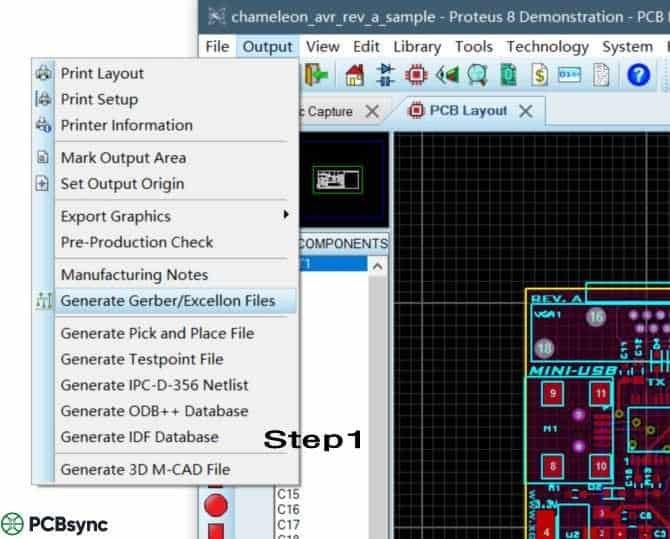
Accessing the Gerber Output Dialog
Navigate to Output > Generate Gerber/Excellon Files from the main menu bar. This opens the Gerber output configuration dialog where you specify export parameters. Alternatively, you can access this function through the Output Jobs Manager for batch processing scenarios.
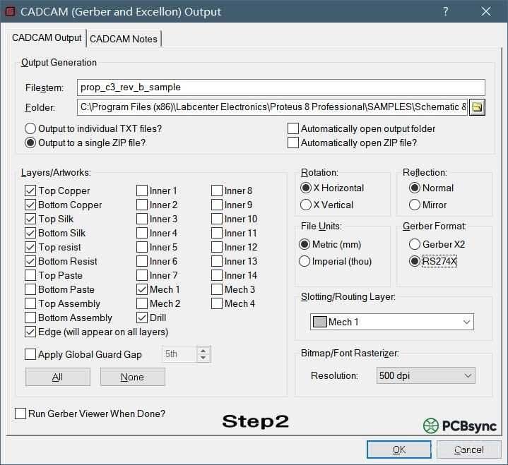
Configuring Output Directory and Archive Settings
Specify your output destination folder in the configuration dialog. Proteus offers the option to consolidate all generated files into a single ZIP archive, which is highly recommended. Most fabrication houses prefer receiving a single compressed package rather than individual files, as this reduces the risk of missing or mismatched files during upload.
Enable the “Output to a single ZIP file” checkbox to activate automatic compression. Name your archive descriptively, incorporating project identifiers and revision numbers for traceability.
Layer Selection and Mapping
The layer selection panel displays all available design layers with corresponding Gerber file assignments. Proteus typically auto-selects the appropriate layers based on your design, but manual verification remains essential.
For a standard two-layer PCB, ensure the following layers are enabled: Top Copper, Bottom Copper, Top Solder Mask, Bottom Solder Mask, Top Silkscreen, Bottom Silkscreen (if populated), Board Outline, and Drill data. Each layer generates a separate file within your output package.
Multi-layer designs require additional selections for internal copper layers and any buried or blind via definitions. Verify that layer polarity settings match your fabricator’s expectations, as inverted polarity can result in catastrophic manufacturing errors.
Format Specification Settings
Set the Gerber format to RS-274X in the format selection dropdown. This extended format includes embedded aperture definitions and represents the current industry standard. Avoid RS-274D unless specifically requested by a legacy manufacturing partner.
Configure coordinate precision based on your design requirements. A 2:5 format (two integer digits, five decimal digits in inches) provides resolution to 0.00001 inches, suitable for most applications. Metric users should select appropriate mm-based precision settings.
Drill File Configuration
Excellon drill files accompany your Gerber package and define all hole locations, sizes, and types. Proteus generates these files automatically when drill layer output is enabled.
Specify whether your drill coordinates should match Gerber units or use separate scaling. Most manufacturers prefer consistent unit systems across all files. Include plated and non-plated hole data as separate files if your design incorporates both types.
Executing the Export
Click OK or Generate to initiate the export process. Proteus processes each selected layer sequentially, generating individual Gerber files and combining them into your specified archive format. A progress indicator displays export status, and any generation errors appear in the output log.
Post-Export Verification Procedures
Never submit Gerber files to manufacturing without independent verification. This quality gate catches export errors, missing layers, and design issues that escaped DRC.
CAM Viewer Inspection
Import your generated Gerber package into a standalone CAM viewer application. Free tools like GerberView, KiCad’s Gerber viewer, or online services such as PCBWay’s Online Gerber Viewer allow layer-by-layer inspection. Verify that copper features, pad shapes, and clearances render correctly across all layers.
Layer Alignment Validation
Check registration between layers by overlaying copper and solder mask files. Solder mask openings should properly expose pads without encroaching on adjacent traces. Silkscreen should not overlap exposed copper or pad areas.
Drill-to-Copper Registration
Overlay drill data on copper layers to confirm via and pad hole placement. Holes should center precisely within annular rings, and any offset indicates coordinate system mismatches or export configuration errors.
Common Issues and Troubleshooting
Several recurring problems affect Proteus Gerber exports. Understanding these issues accelerates troubleshooting when files fail manufacturer review.
Missing apertures typically indicate incomplete library definitions or custom pad shapes that lack proper flash assignments. Regenerate pads from library components or manually define apertures in the Proteus aperture editor.
Inverted layers occur when polarity settings conflict with manufacturer expectations. Some fabricators interpret solder mask as positive (exposed areas defined) while others expect negative (covered areas defined). Clarify polarity conventions before submission.
Coordinate offset errors place design features at unexpected positions. Verify that your design origin matches the Gerber output origin, and consider centering your design on the origin point to avoid negative coordinate complications.
Manufacturer Submission Best Practices
When submitting your Gerber package, include a fabrication drawing or README file specifying critical parameters: board dimensions, layer count, copper weight, surface finish, solder mask color, and any special requirements. This documentation prevents misinterpretation and establishes clear expectations.
Request a DFM (Design for Manufacturability) review from your fabricator before authorizing production. Most PCB manufacturers offer free file verification that catches issues automated tools might miss.
Conclusion
Generating Gerber files from Proteus requires attention to configuration details and systematic verification procedures. By following the workflow outlined above, engineers can produce manufacturing-ready files that translate designs accurately to physical boards. The combination of proper DRC validation, correct export settings, and independent Gerber verification establishes a reliable pipeline from Proteus design to fabricated PCB.
Remember that fabrication requirements vary between manufacturers, so always consult your chosen supplier’s design guidelines before finalizing export parameters. This proactive approach minimizes revision cycles and accelerates your path from prototype to production.
Inquire: Call 0086-755-23203480, or reach out via the form below/your sales contact to discuss our design, manufacturing, and assembly capabilities.
Quote: Email your PCB files to Sales@pcbsync.com (Preferred for large files) or submit online. We will contact you promptly. Please ensure your email is correct.
Notes: For PCB fabrication, we require PCB design file in Gerber RS-274X format (most preferred), *.PCB/DDB (Protel, inform your program version) format or *.BRD (Eagle) format. For PCB assembly, we require PCB design file in above mentioned format, drilling file and BOM. Click to download BOM template To avoid file missing, please include all files into one folder and compress it into .zip or .rar format.


