Inquire: Call 0086-755-23203480, or reach out via the form below/your sales contact to discuss our design, manufacturing, and assembly capabilities.
Quote: Email your PCB files to Sales@pcbsync.com (Preferred for large files) or submit online. We will contact you promptly. Please ensure your email is correct.
Notes: For PCB fabrication, we require PCB design file in Gerber RS-274X format (most preferred), *.PCB/DDB (Protel, inform your program version) format or *.BRD (Eagle) format. For PCB assembly, we require PCB design file in above mentioned format, drilling file and BOM. Click to download BOM template To avoid file missing, please include all files into one folder and compress it into .zip or .rar format.
If you’ve spent any time on a PCB assembly line, you know that catching defects early saves headaches later. That’s where functional test comes in. As someone who’s been in electronics manufacturing for years, I can tell you that FCT (Functional Circuit Test) remains one of the most reliable ways to verify that your assembled boards actually work the way they should.
In this guide, I’ll walk you through everything you need to know about functional test in electronics manufacturing, from basic principles to advanced implementation strategies. Whether you’re setting up your first test station or optimizing an existing process, you’ll find practical insights here.
Functional test, commonly abbreviated as FCT, is a quality control method used in electronics manufacturing to verify that a printed circuit board assembly (PCBA) operates according to its design specifications. Unlike other testing methods that check individual components or solder joints, functional test evaluates the board as a complete working system.
Think of it this way: ICT (In-Circuit Test) asks “are the parts installed correctly?” while functional test asks “does this thing actually work?”
During a functional test, the PCBA is powered up and subjected to various input signals. The test system then measures the outputs to confirm they match expected values. This approach catches defects that other testing methods might miss, including firmware bugs, timing issues, and component interactions that only show up under real operating conditions.
Why Functional Test Matters in PCBA Production
Here’s a reality check from the production floor: even boards that pass ICT can fail in the field. I’ve seen it happen more times than I’d like to admit. A board passes all component-level checks but fails when the customer plugs it in. That’s expensive, embarrassing, and entirely preventable with proper functional testing.
Functional test catches problems like:
Firmware or software bugs
Signal integrity issues under load
Timing problems between components
Power supply regulation under actual conditions
Communication protocol failures
Analog circuit performance outside specs
How Does Functional Test Work?
The functional test process follows a logical sequence that mimics real-world operation. Here’s how it typically plays out on the production line.
The Functional Test Process Step by Step
Step 1: Fixture Connection
The PCBA is placed into a test fixture that connects to key test points, connectors, and interfaces on the board. This fixture might use pogo pins, edge connectors, or cable assemblies depending on the board design.
Step 2: Power Application
The test system applies power to the board, usually monitoring current draw during startup. Abnormal current consumption often indicates shorts or component failures before any functional checks begin.
Step 3: Initialization Sequence
For boards with microcontrollers or processors, the test system verifies proper boot-up, firmware loading, and initialization routines. This might include checking boot messages, LED sequences, or communication handshakes.
Step 4: Stimulus and Response Testing
The test system applies various inputs (signals, commands, data) and measures the corresponding outputs. This is the core of functional testing where actual circuit behavior gets verified against expected results.
Step 5: Boundary Condition Testing
Good functional test routines push the board to its limits, checking operation at voltage extremes, temperature boundaries, and maximum load conditions.
Step 6: Final Verification and Logging
All test results are logged for traceability, and the board receives a pass/fail determination based on predefined criteria.
Key Components of a Functional Test System
A complete functional test station includes several essential elements:
Component
Function
Example Equipment
Test Fixture
Physical interface to the PCBA
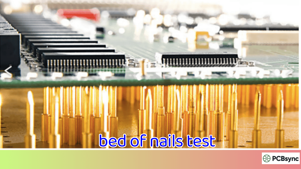
Custom pogo pin fixtures, bed-of-nails
Power Supply
Provides operating voltage
Programmable DC supplies (Keysight, Keithley)
Signal Generator
Creates test stimuli
Function generators, arbitrary waveform generators
Types of Functional Test in Electronics Manufacturing
Not all functional tests are created equal. The approach you choose depends on your product complexity, production volume, and quality requirements.
Hot Mock-Up Testing
This approach uses actual peripheral devices or loads connected to the board. For example, testing a motor controller by connecting it to a real motor. It’s the closest thing to real-world operation but can be slow and expensive for high-volume production.
Simulation-Based Functional Test
Here, electronic loads and signal simulators replace actual peripherals. A motor controller might be tested with an electronic load that mimics motor characteristics. This approach balances test coverage with production speed.
Boundary Scan Functional Test
For complex digital boards, boundary scan (JTAG) can supplement traditional functional testing. It allows testing of digital I/O, memory interfaces, and processor functions without physical access to every test point.
Automated Functional Test (AFT)
In high-volume manufacturing, fully automated functional test systems handle board loading, testing, and sorting without operator intervention. These systems often combine multiple test methods in a single station.
Functional Test vs Other PCB Testing Methods
Understanding where functional test fits in your overall test strategy is crucial. Here’s how it compares to other common methods.
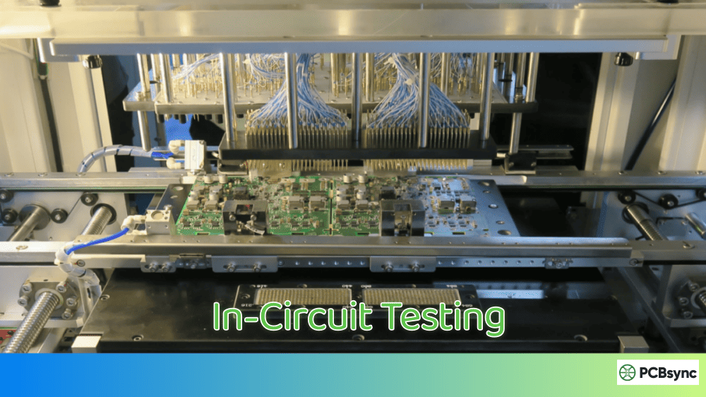
Functional Test vs ICT (In-Circuit Test)
Aspect
Functional Test
ICT (In-Circuit Test)
What It Tests
Board operation as a system
Individual components and connections
Catches
Firmware bugs, timing issues, system integration problems
Opens, shorts, wrong values, missing parts
Fixture Cost
Moderate to high
High (bed-of-nails)
Test Speed
Slower (seconds to minutes)
Fast (seconds)
Design Access
Needs key interfaces
Needs test points on every net
Best For
Complex, software-driven boards
High-volume, mature designs
Functional Test vs AOI (Automated Optical Inspection)
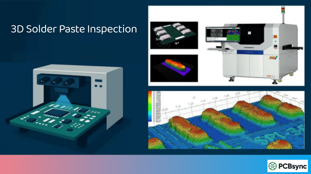
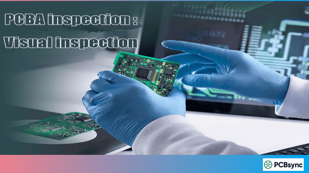
AOI inspects solder joints and component placement visually. It’s great for catching assembly defects but tells you nothing about whether the board actually functions. Functional test picks up where AOI leaves off.
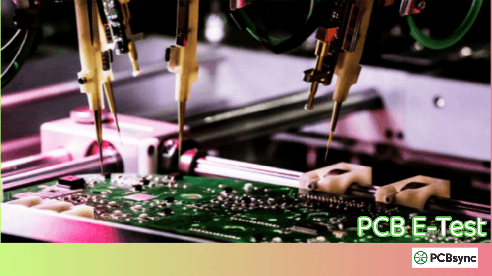
Functional Test vs Flying Probe
Flying probe testing offers flexibility without custom fixtures but is slower than ICT and doesn’t provide the operational verification that functional test delivers. Many manufacturers use flying probe for prototype runs and transition to functional test for production.
When to Use Each Testing Method
The smart approach combines multiple methods:
Production Stage
Recommended Testing
Prototype/NPI
Flying probe + basic functional test
Low Volume (<1000/year)
AOI + functional test
Medium Volume
AOI + ICT + functional test
High Volume
AOI + ICT + automated functional test
Designing for Functional Test: Practical Tips
I’ve seen too many designs that are impossible to test efficiently. Here’s what to consider during the design phase to make functional testing practical.
Test Point Accessibility
Include dedicated test points for critical signals. Don’t assume you can probe fine-pitch components or hidden BGA balls. A few strategically placed test points save enormous headaches later.
Connector Strategy
Design your board with test connectors in mind. Even if the production unit uses a specific connector, consider adding a secondary interface specifically for testing.
Built-In Self-Test (BIST)
For microcontroller-based designs, implement BIST routines in firmware. A dedicated test mode that exercises peripherals and reports results dramatically simplifies external test requirements.
Power Sequencing
Design for easy power control during testing. Separate power rails, test enable signals, and proper power-up sequences make functional testing more reliable.
Common Functional Test Challenges and Solutions
After years of setting up functional test stations, I’ve encountered most of the common problems. Here’s how to handle them.
Challenge 1: Long Test Times
Problem: Test sequences take too long for production throughput.
Solutions:
Parallel testing where possible
Optimize test sequence order
Use faster measurement equipment
Implement adaptive testing (skip tests based on earlier results)
Challenge 2: False Failures
Problem: Good boards fail due to test system issues, not actual defects.
Solutions:
Tighten fixture maintenance schedules
Implement proper grounding and shielding
Use statistical process control to identify drift
Add retry logic for marginal measurements
Challenge 3: Fixture Wear
Problem: Pogo pins and contacts wear out, causing intermittent connections.
Solutions:
Track fixture cycles and schedule preventive replacement
Use higher-quality contact materials
Design fixtures with replaceable contact modules
Monitor contact resistance as a maintenance indicator
Challenge 4: Test Coverage Gaps
Problem: Some functions aren’t tested, leading to field failures.
Solutions:
Conduct thorough failure mode analysis during test development
Review field return data and add tests for recurring issues
Implement boundary condition testing
Consider environmental stress screening for critical products
Functional Test Equipment and Software
Building an effective functional test station requires the right tools. Here’s what you’ll typically need.
Hardware Requirements
Essential equipment:
Programmable power supplies (multiple channels for complex boards)
Digital multimeters (6.5 digit for precision measurements)
Oscilloscopes (for timing and signal integrity checks)
Logic analyzers (for digital communication verification)
Electronic loads (for power supply testing)
Communication interfaces:
USB/serial adapters for UART communication
SPI/I2C protocol adapters
CAN/LIN interfaces for automotive applications
Ethernet switches for networked devices
Software Platforms for Functional Test
Platform
Best For
Learning Curve
LabVIEW
Complex test systems, NI hardware integration
Steep
TestStand
Production test management, reporting
Moderate
Python + PyVISA
Flexible, cost-effective solutions
Moderate
Keysight OpenTAP
Open-source test automation
Moderate
Custom C#/.NET
Windows-based proprietary systems
Steep
For most small to medium operations, Python-based solutions offer the best balance of flexibility and cost. LabVIEW remains the industry standard for complex systems but carries significant licensing costs.
Functional Test Best Practices
After debugging countless test stations, here are the practices that actually make a difference.
Document Everything
Maintain detailed test specifications including pass/fail limits, test sequences, and fixture requirements. When something goes wrong six months later, you’ll thank yourself for the documentation.
Version Control Your Test Code
Treat test software like production code. Use Git or another version control system. Track changes and maintain the ability to roll back when updates cause problems.
Establish Statistical Limits
Don’t just set pass/fail limits based on datasheet specs. Collect data from known-good boards and establish limits based on actual production variation. This reduces false failures and catches real defects earlier.
Plan for Maintenance
Test fixtures and equipment need regular maintenance. Build this into your production schedule rather than waiting for failures.
Correlate with Field Data
Regularly review field failure data and adjust your functional test coverage. The test that catches 0.1% additional defects might save significant warranty costs.
Useful Resources for Functional Test Implementation
Here are some resources I’ve found valuable over the years:
Standards and Guidelines:
IPC-9252: Requirements for Electrical Testing of Unpopulated Printed Boards
IPC/JEDEC J-STD-001: Requirements for Soldered Electrical and Electronic Assemblies
“The Art of Electronics” by Horowitz and Hill (circuit fundamentals)
National Instruments Application Notes on Test System Design
IPC Training and Certification Programs
The Future of Functional Test in Electronics Manufacturing
The functional test landscape is evolving. Here are trends worth watching:
AI and Machine Learning: Test systems are beginning to use ML algorithms to optimize test sequences, predict failures, and identify patterns in test data that humans might miss.
Cloud-Connected Test Systems: Remote monitoring, data analytics, and test program updates are moving to cloud platforms, enabling better visibility across multiple manufacturing sites.
Digital Twins: Virtual models of products are being used to develop and validate test strategies before physical prototypes exist, reducing test development time.
Integration with MES: Tighter integration between functional test systems and Manufacturing Execution Systems provides better traceability and real-time quality visibility.
Frequently Asked Questions About Functional Test
What is the difference between functional test and ICT?
Functional test verifies that a board operates correctly as a complete system by applying power and testing actual operation. ICT (In-Circuit Test) checks individual components and connections without powering up the board as a working system. Think of ICT as checking that all the parts are there and connected, while functional test confirms the assembled product actually works. Most production lines benefit from using both methods together.
How long does a typical functional test take?
Test duration varies widely based on product complexity. Simple boards might complete functional testing in 10-30 seconds. Complex products with extensive firmware verification, communication testing, and multiple operating modes can require several minutes. High-volume production often uses parallel testing or abbreviated test sequences to maintain throughput while preserving adequate coverage.
Can functional test replace other testing methods?
Functional test alone cannot catch all defects. It’s excellent for verifying system operation but may miss component-level issues that don’t immediately affect function. For example, a marginally soldered joint might pass functional test but fail in the field under thermal cycling. The best approach combines functional test with visual inspection (AOI) and electrical testing (ICT or flying probe) for comprehensive coverage.
What skills are needed to develop functional test programs?
Effective functional test development requires a combination of skills: understanding of the product’s circuit design and operation, proficiency in test software platforms (LabVIEW, Python, TestStand), knowledge of measurement techniques and equipment, and familiarity with communication protocols used by the product. Experience with fixture design and production environment requirements is also valuable.
How do I calculate ROI for investing in functional test equipment?
Calculate functional test ROI by comparing the cost of the test system (equipment, fixtures, development time, ongoing maintenance) against the savings from catching defects before shipment. Consider warranty costs, customer returns, reputation damage, and production time lost to troubleshooting field failures. Most manufacturers find that products with >1000 annual units justify dedicated functional test investment, though critical applications may warrant testing at any volume.
About the Author: This guide was written from practical experience in PCB assembly and test engineering. The recommendations reflect real-world production environments and lessons learned from implementing functional test systems across various product types.
Inquire: Call 0086-755-23203480, or reach out via the form below/your sales contact to discuss our design, manufacturing, and assembly capabilities.
Quote: Email your PCB files to Sales@pcbsync.com (Preferred for large files) or submit online. We will contact you promptly. Please ensure your email is correct.
Notes: For PCB fabrication, we require PCB design file in Gerber RS-274X format (most preferred), *.PCB/DDB (Protel, inform your program version) format or *.BRD (Eagle) format. For PCB assembly, we require PCB design file in above mentioned format, drilling file and BOM. Click to download BOM template To avoid file missing, please include all files into one folder and compress it into .zip or .rar format.


