Inquire: Call 0086-755-23203480, or reach out via the form below/your sales contact to discuss our design, manufacturing, and assembly capabilities.
Quote: Email your PCB files to Sales@pcbsync.com (Preferred for large files) or submit online. We will contact you promptly. Please ensure your email is correct.
Notes: For PCB fabrication, we require PCB design file in Gerber RS-274X format (most preferred), *.PCB/DDB (Protel, inform your program version) format or *.BRD (Eagle) format. For PCB assembly, we require PCB design file in above mentioned format, drilling file and BOM. Click to download BOM template To avoid file missing, please include all files into one folder and compress it into .zip or .rar format.
If you’ve ever had a batch of 500 PCBAs come off the SMT line only to discover that a capacitor was loaded in the wrong orientation—on every single board—you know the gut-punch feeling. Thousands of dollars in rework, delayed shipments, and an uncomfortable conversation with your customer.
That scenario is exactly what first article inspection is designed to prevent.
I’ve spent over a decade working with SMT lines, and I can tell you that FAI isn’t just another checkbox on your quality paperwork. It’s the gatekeeper that catches programming errors, wrong components, and process problems before they multiply across your entire production run.
In this guide, I’ll walk you through everything you need to know about implementing an effective first article inspection process in your SMT assembly operation—from the basics to advanced automated systems that can cut your inspection time by 80%.
First article inspection (FAI) is a complete, documented physical and functional inspection performed on the first assembled PCB from a production run. The purpose is straightforward: verify that the SMT line setup is correct before committing to full production.
When your SMT line finishes assembling that first board, it gets pulled and inspected against:
The bill of materials (BOM)
Assembly drawings and CAD data
Customer specifications
Gerber files and pick-and-place coordinates
Think of FAI as your manufacturing sanity check. It confirms that every component is the right part, in the right place, with the correct orientation—before you run hundreds or thousands more boards.
First Article Inspection vs. Prototypes: What’s the Difference?
Here’s a common misconception I see: people confuse first articles with prototypes.
They’re not the same thing.
Prototypes are built using different processes—sometimes hand-soldered, often on different equipment, typically in engineering rather than production. They validate your design.
First articles come directly off your production SMT line using the exact same equipment, programs, and processes that will build the entire batch. They validate your manufacturing setup.
This distinction matters because a prototype that works perfectly tells you nothing about whether your pick-and-place machine is programmed correctly or whether your feeders are loaded with the right reels.
Why First Article Inspection is Critical for Preventing Batch Defects
The math on SMT defects is brutal.
A typical PCB might have 300-400 surface mount components. Each component has multiple solder terminations. That means a single board can have 1,000+ opportunities for something to go wrong.
Now multiply that across a production run of 500 boards.
If your pick-and-place machine has the wrong component loaded in feeder slot 23, every single board will have that wrong component. If your reflow profile is causing tombstoning on your 0402 capacitors, you’ll see that defect replicated across the entire batch.
First article inspection catches these systematic errors after one board—not after 500.
The Real Cost of Skipping FAI
Let me share some numbers from actual production scenarios:
The pattern is clear: FAI transforms potential batch disasters into minor corrections.
Common Defects That FAI Catches Early
Based on my experience, here are the issues first article inspection most frequently catches:
Defect Type
Root Cause
How FAI Catches It
Wrong component value
Incorrect BOM entry or feeder loading
LCR measurement comparison to BOM
Reversed polarity
Programming error or feeder setup
Visual inspection against assembly drawing
Missing components
Feeder empty or pick failure
Cross-reference with BOM, visual check
Tombstoning
Reflow profile issue, pad imbalance
Visual inspection, process review
Component misalignment
Pick-and-place program offset
Comparison to CAD placement data
Wrong package size
Incorrect component in feeder
Physical measurement, visual check
Solder bridges
Stencil issues, paste volume
Visual and electrical testing
The Complete First Article Inspection Process
Let me walk you through how a proper FAI should work in practice.
Step 1: Document Preparation and Review
Before your first board even hits the SMT line, gather and verify all documentation:
Required documents:
Current revision BOM with all approved alternates clearly marked
Assembly drawings with reference designators
Gerber files
Pick-and-place coordinate file
Any engineering change notices (ECNs)
Customer specifications and workmanship requirements
Pro tip: I’ve seen countless FAI failures traced back to working from outdated documentation. Always confirm you have the latest revision before starting.
Step 2: SMT Line Setup Verification
Before running the first article:
Verify solder paste lot number, expiration date, and proper storage
Confirm stencil matches the PCB revision
Check all feeder assignments against the BOM
Review pick-and-place program for correct X/Y coordinates and rotations
Verify reflow profile is validated for this assembly
This pre-production verification catches obvious setup errors before wasting even a single board.
Step 3: First Article Sample Production
Run your first board through the complete SMT process:
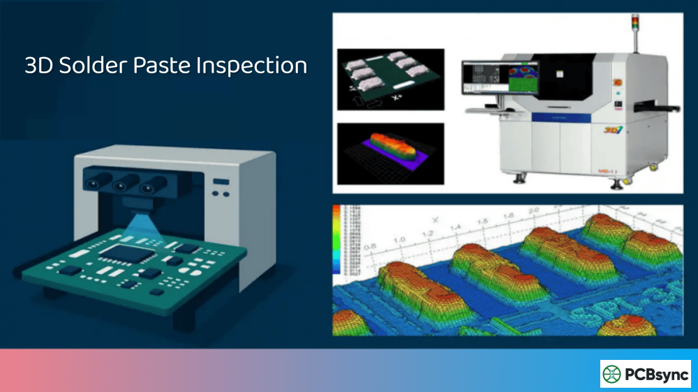
Solder paste printing
Solder paste inspection (SPI) if available
Pick-and-place component mounting
Pre-reflow inspection (optional but recommended)
Reflow soldering
Post-reflow cooling
The key here is that this board must go through exactly the same process as production boards. Don’t hand-place components or use different equipment.
Step 4: Detailed First Article Inspection
Now comes the actual inspection. This is where you systematically verify every aspect of the assembly.
Component verification checklist:
Inspection Point
Method
Acceptance Criteria
Component presence
Visual, BOM comparison
All BOM items present
Component values
LCR meter measurement
Within specified tolerance
Polarity/orientation
Visual vs. assembly drawing
Matches documentation
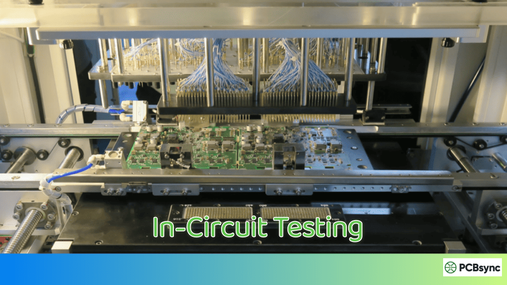
Placement accuracy
Visual, AOI, or CMM
Within IPC-A-610 limits
Solder joint quality
Visual, X-ray for BGAs
Per IPC-A-610 class requirements
Marking/labeling
Visual inspection
Readable, correctly positioned
For BGA and hidden solder joints: X-ray inspection is essential. You cannot visually verify solder ball connections under a BGA package.
Step 5: Documentation and Sign-Off
Every FAI must be documented. Your FAI report should include:
Part number and revision
Serial number of inspected unit
Date and inspector identification
Results for each inspection point
Any deviations found and corrective actions taken
Approval signatures
This documentation becomes part of your quality records and may be required by your customers, especially in aerospace, medical, and automotive industries.
Step 6: Corrective Action for FAI Failures
When first article inspection reveals problems—and it will, that’s the whole point—you need a clear corrective action process.
Typical FAI failure scenarios and responses:
Failure Type
Immediate Action
Root Cause Investigation
Wrong component loaded
Replace feeder, rebuild first article
Verify BOM-to-feeder assignment process
Component orientation error
Correct pick-and-place program
Review CAD data import process
Placement offset
Adjust machine offset, rebuild
Check vision calibration
Solder defects
Review reflow profile, stencil
Verify paste age, profile settings
Missing component
Check feeder, nozzle condition
Evaluate pick failure rate
The key is not just fixing the immediate problem but understanding why it happened. If your pick-and-place program had a rotation error, was it a one-time data entry mistake or a systematic problem with how you import CAD data?
Document corrective actions in your FAI report. This creates a knowledge base that helps prevent similar issues on future builds.
First Article Inspection Methods: Manual vs. Automated
The traditional FAI process—two inspectors with a microscope, BOM printout, and loading diagram—can take 2-3 hours for a complex board with 300+ components. That’s 2-3 hours of your expensive pick-and-place equipment sitting idle.
Modern SMT operations are increasingly turning to automated FAI systems to speed this up.
Manual First Article Inspection
How it works: Inspectors visually examine each component under magnification, comparing part markings, orientations, and placement against the BOM and assembly drawing. LCR measurements verify passive component values.
Pros:
Lower equipment cost
Flexible for any board design
Effective for low-volume, high-mix production
Cons:
Time-consuming (1-3 hours per board)
Subject to human error and fatigue
Difficult to maintain consistency
Documentation is often manual
Automated First Article Inspection Systems
How it works: Automated FAI systems integrate BOM data, CAD coordinates, and scanned images of the actual PCB. The software guides the operator through inspection, automatically comparing measurements and flagging discrepancies.
Popular automated FAI system features:
Feature
Benefit
BOM-to-CAD integration
Automatic correlation of part numbers to positions
LCR auto-measurement
Eliminates manual probe positioning
Image comparison
Golden board comparison for visual verification
Automated reporting
FAI reports generated with one click
Barcode scanning
Verify component reels match BOM
Database storage
Historical FAI records for audit trails
Pros:
80%+ reduction in inspection time
Higher consistency and accuracy
Automatic documentation
Reduced inspector training requirements
Cons:
Initial equipment investment ($15,000-50,000+)
Setup time for each new product
May require CAD data in specific formats
When to Use Each Method
Production Scenario
Recommended Approach
Low-volume prototypes (<10 boards)
Manual FAI
High-mix production with frequent changeovers
Automated FAI
High-volume single product
Automated FAI with golden board
Aerospace/medical with AS9102 requirements
Automated FAI for documentation
Simple boards (<50 components)
Manual FAI may suffice
Complex boards (>200 components)
Automated FAI strongly recommended
Industry Standards for First Article Inspection
Understanding the relevant standards helps ensure your FAI process meets customer and regulatory requirements.
IPC-A-610: Acceptability of Electronic Assemblies
IPC-A-610 is the globally recognized standard for visual acceptance criteria. It defines three classes of products:
Your first article inspection should evaluate workmanship against the appropriate IPC-A-610 class specified by your customer.
AS9102: Aerospace First Article Inspection
If you’re supplying aerospace or defense customers, AS9102 is the standard you need to know. It’s specifically designed for production process verification in the AS&D industry.
AS9102 requires three forms:
Form 1: Part number accountability
Form 2: Product accountability (materials, processes, special requirements)
Form 3: Characteristic accountability (all dimensions and specifications)
The latest revision is AS9102C (released 2023), which emphasizes FAI planning, evaluation, and re-accomplishment activities.
J-STD-001: Requirements for Soldered Electrical and Electronic Assemblies
While IPC-A-610 covers acceptance criteria (what a good assembly looks like), J-STD-001 addresses process requirements (how to build it correctly). Your FAI should verify that soldering meets J-STD-001 requirements.
Setting Up an Effective FAI Process in Your SMT Operation
Based on my experience implementing FAI processes across multiple facilities, here are the practical steps to get it right.
Create Clear FAI Procedures
Document your FAI process in a procedure that covers:
Trigger conditions (new product, design change, new supplier, process change)
Required documentation and who provides it
Inspection steps and acceptance criteria
Equipment and tools required
Documentation requirements
Approval authority and escalation paths
Train Your Inspectors
FAI inspection requires different skills than production operators. Your FAI inspectors need:
Understanding of SMT components and packaging
Ability to read and interpret BOMs, assembly drawings, and Gerbers
Proficiency with inspection equipment (microscopes, LCR meters, X-ray if applicable)
Knowledge of applicable standards (IPC-A-610, J-STD-001, customer specs)
Documentation skills
Consider IPC-A-610 certification for your inspection staff.
Invest in Proper Equipment
At minimum, a manual FAI station needs:
Stereo microscope with adequate magnification (10x-45x typical)
Good lighting (ring lights work well)
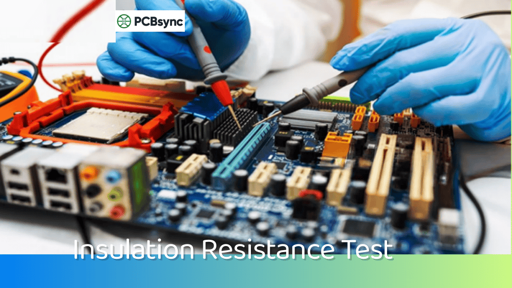
LCR meter for passive component verification
Calipers and measurement tools
Access to X-ray for BGA inspection
For higher volumes, automated FAI systems pay for themselves quickly in reduced inspection time and improved accuracy.
Integrate FAI into Your Production Flow
FAI shouldn’t be an afterthought. Build it into your production scheduling:
Schedule adequate time between first article completion and production start
Don’t start production until FAI is approved
Have contingency plans for FAI failures (who decides, how fast can corrections be made)
Track FAI metrics (pass rate, common failure modes, inspection time)
Common First Article Inspection Mistakes to Avoid
I’ve seen plenty of FAI processes that look good on paper but fail in practice. Here are the pitfalls to watch for:
Rushing the Inspection
When expensive SMT equipment sits idle waiting for FAI approval, there’s enormous pressure to hurry. Resist it. A thorough 90-minute inspection is far cheaper than reworking 500 boards because you missed a wrong component.
Working from Outdated Documentation
Always verify you have the current BOM revision. I’ve seen FAI pass, production run, and then someone realizes the BOM was two revisions old. Not a fun day.
Skipping FAI for “Minor” Changes
Even small engineering changes can have unexpected effects. Changed a resistor value? The new part might have different packaging that requires pick-and-place adjustment. Always do FAI after changes.
Not Documenting Findings
“We looked at it and it was fine” isn’t documentation. Proper records protect you when customers ask questions months later.
Ignoring Process Indicators
FAI isn’t just about finding defects—it’s about spotting process indicators that could become defects under production conditions. That slightly skewed component might pass specifications but indicates a placement issue that will get worse.
Real-World Case Study: How FAI Saved a Production Run
Let me share a real example from a contract manufacturer I worked with.
They were building a power supply controller board—about 280 components, medium complexity. The customer had provided an updated BOM with a new alternate capacitor that had just been approved.
During first article inspection, the inspector noticed something odd. The new alternate capacitor was physically larger than the original. Not by much—just 0.3mm longer. But it was enough that the component was touching the adjacent resistor.
On its own, this wasn’t a defect. The components weren’t shorting. The board would have passed AOI.
But here’s what would have happened in production: during reflow, thermal expansion would cause these touching components to push against each other. Over thermal cycles in the field, this mechanical stress would eventually crack solder joints.
The FAI caught this. Engineering modified the layout to add clearance. The customer got reliable boards instead of field failures six months later.
That’s the value of first article inspection. It’s not just catching obvious errors—it’s catching the subtle issues that become big problems down the road.
Advanced First Article Inspection Techniques
For operations dealing with high-reliability products or complex assemblies, standard FAI may not be enough.
Golden Board Comparison
Some automated FAI systems support “golden board” methodology:
Build and thoroughly validate a reference board (the golden board)
Use automated optical comparison to verify subsequent first articles match the golden board
Any visual differences are flagged for review
This approach is particularly effective for catching cosmetic issues and subtle placement variations that might be missed in component-by-component inspection.
Statistical FAI for High-Volume Production
For very high-volume production runs, some manufacturers use statistical FAI approaches:
Approach
Description
Best For
Single unit FAI
Traditional—inspect first board completely
Standard approach
Three-board FAI
Inspect three boards from first run
Higher confidence, complex assemblies
Statistical sampling
Inspect random sample from first panel
Very high volume, low complexity
The tradeoff is inspection time versus confidence level. For high-reliability applications, I always recommend full FAI on at least one board, regardless of volume.
First Article Inspection for Lead-Free and Mixed Technology
Lead-free assembly and mixed technology boards (combining SMT and through-hole) present additional FAI challenges:
Lead-free considerations:
Higher reflow temperatures require more careful profile validation
Lead-free solder joints have different visual appearance than leaded
Some components may not be rated for lead-free temperatures
Mixed technology considerations:
Wave solder or selective solder process must be validated separately
Through-hole component inspection criteria differ from SMT
Process sequence (SMT first, then through-hole) must be verified
Useful Resources for First Article Inspection
Here are resources I recommend for anyone looking to improve their FAI process:
If you’re considering automated FAI equipment, these are established vendors worth evaluating:
Cogiscan
Mentor (Siemens)
Aegis Software
Juki
Orbotech
Frequently Asked Questions About First Article Inspection
When is a first article inspection required?
You should perform FAI for:
New products: Any PCB assembly being built for the first time
Design changes: After ECNs that affect components, placement, or process
Process changes: New equipment, new solder paste, changed reflow profile
Supplier changes: New component suppliers or alternate parts
Production resumption: After extended production gaps (typically 6+ months)
Customer requirements: Whenever specified by contract or purchase order
How long should a first article inspection take?
It depends on board complexity and method. Manual FAI for a board with 300 components typically takes 1.5-3 hours. Automated FAI systems can reduce this to 15-30 minutes. Simple boards with fewer than 50 components might only need 30-45 minutes for manual inspection.
Can first article inspection be performed by the same person who set up the line?
Best practice says no. Independence is a key principle of FAI—the inspector should not be the same person who created the setup being verified. This provides a fresh set of eyes and prevents blind spots. Many quality standards explicitly require independent verification.
What’s the difference between FAI and in-process inspection?
First article inspection happens before production begins and verifies the complete setup against all documentation. In-process inspection (like AOI) happens during production and checks for manufacturing defects on individual boards. Both are important, but they serve different purposes. FAI catches systematic errors; in-process inspection catches random defects.
Do I need X-ray inspection for FAI?
If your assembly includes BGAs, QFNs, or other components with hidden solder joints, yes. You cannot visually verify solder connections under these packages. X-ray inspection is the only way to confirm proper solder ball collapse and joint formation on hidden connections.
Conclusion: Making First Article Inspection Work for Your Operation
First article inspection isn’t glamorous. It doesn’t involve the latest AI or Industry 4.0 buzzwords. But it’s one of the most effective quality tools in SMT manufacturing.
Done right, FAI is the firewall that prevents a single programming error from becoming a warehouse full of defective boards.
The key points to remember:
FAI validates your production setup, not your design
Systematic errors multiply across entire production runs
Documentation matters—for your quality records and your customers
Invest in training and equipment appropriate to your production volume
Never skip FAI for “minor” changes
If you’re currently struggling with batch defects or customer complaints about workmanship, take a hard look at your first article inspection process. It might be the most impactful improvement you can make.
Whether you’re running a small prototype shop or a high-volume contract manufacturing operation, the principles remain the same: catch errors early, document everything, and never let time pressure compromise your inspection thoroughness.
The time you invest in thorough FAI at the start of a production run will save you exponentially more time in rework, customer complaints, and quality investigations later.
Start by auditing your current FAI process. Are you catching systematic errors before production? Is your documentation complete enough to satisfy customer audits? Are your inspectors trained and equipped properly?
If you answered “no” to any of these questions, you know where to focus your improvement efforts.
Your future self—and your customers—will thank you.
Inquire: Call 0086-755-23203480, or reach out via the form below/your sales contact to discuss our design, manufacturing, and assembly capabilities.
Quote: Email your PCB files to Sales@pcbsync.com (Preferred for large files) or submit online. We will contact you promptly. Please ensure your email is correct.
Notes: For PCB fabrication, we require PCB design file in Gerber RS-274X format (most preferred), *.PCB/DDB (Protel, inform your program version) format or *.BRD (Eagle) format. For PCB assembly, we require PCB design file in above mentioned format, drilling file and BOM. Click to download BOM template To avoid file missing, please include all files into one folder and compress it into .zip or .rar format.


