Inquire: Call 0086-755-23203480, or reach out via the form below/your sales contact to discuss our design, manufacturing, and assembly capabilities.
Quote: Email your PCB files to Sales@pcbsync.com (Preferred for large files) or submit online. We will contact you promptly. Please ensure your email is correct.
Notes: For PCB fabrication, we require PCB design file in Gerber RS-274X format (most preferred), *.PCB/DDB (Protel, inform your program version) format or *.BRD (Eagle) format. For PCB assembly, we require PCB design file in above mentioned format, drilling file and BOM. Click to download BOM template To avoid file missing, please include all files into one folder and compress it into .zip or .rar format.
If you’ve been designing antenna circuits for cellular base stations or WiMAX networks, chances are you’ve come across the challenge of balancing performance with cost. That’s exactly where RO4500 PCB materials shine. After years of working with various high-frequency substrates, I can tell you that Rogers’ RO4500 series has carved out a unique position in the antenna laminate market—offering near-PTFE performance at a fraction of the cost.
In this guide, I’ll walk you through everything you need to know about RO4500 PCB materials: from technical specifications and material variants to design considerations and fabrication tips. Whether you’re specifying materials for a new project or evaluating alternatives to your current substrate, this comprehensive breakdown will help you make an informed decision.
Understanding Search Intent: Who Needs RO4500 PCB Information?
Before diving into the technical details, it’s worth understanding why engineers search for RO4500 PCB information. In my experience, there are typically three types of searches:
Material Selection Engineers are comparing options for a new antenna project. They need comparative data, specifications, and application guidance to make procurement decisions.
RF Design Engineers already know they’re using RO4500 and need detailed specifications for their impedance calculations, stack-up planning, and performance predictions.
Production Engineers are troubleshooting fabrication issues or qualifying a new supplier. They need processing parameters and compatibility information.
This guide addresses all three needs, but I’ve organized it so you can jump directly to the sections most relevant to your situation. If you’re in a hurry, the specification tables and comparison sections will give you quick answers. If you’re doing a deep evaluation, the design considerations and fabrication guidelines will prove valuable.
What is RO4500 PCB Material?
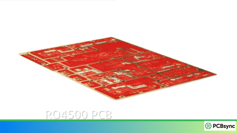
RO4500 PCB is an antenna-grade, high-frequency laminate developed by Rogers Corporation. It belongs to the broader RO4000 product family—a series of hydrocarbon ceramic laminates that have become industry standards for RF and microwave applications.
What makes RO4500 unique is its specific engineering for commercial antenna applications. Unlike general-purpose RF laminates, Rogers designed this material from the ground up to address the demands of high-volume wireless infrastructure, particularly cellular base station antennas and broadband wireless access systems.
The material is a ceramic-filled, glass-fiber-reinforced hydrocarbon-based composite. This composition gives it a controlled dielectric constant, low signal loss, and excellent passive intermodulation (PIM) response—three properties that antenna engineers care deeply about.
Material Composition and Structure
Understanding the composition helps explain why RO4500 performs the way it does. The laminate consists of several key components:
Hydrocarbon Resin System: Unlike PTFE-based materials, RO4500 uses a thermoset hydrocarbon resin. This provides the FR-4 processing compatibility while maintaining low-loss characteristics.
Ceramic Filler: Carefully selected ceramic particles are dispersed throughout the resin matrix. These fillers control the dielectric constant and improve thermal conductivity. The filler distribution is tightly controlled to ensure Dk uniformity across the panel.
Glass Fiber Reinforcement: Woven E-glass fabric provides mechanical strength and dimensional stability. The glass weave also contributes to the material’s consistent CTE characteristics.
Copper Foil: Standard electrodeposited (ED) copper or low-profile (LoPro) copper foils are bonded to the dielectric. The choice of foil affects surface roughness, which impacts conductor loss at high frequencies and PIM performance.
The RO4500 Series Variants
Rogers offers three main variants within the RO4500 series, each with slightly different dielectric constants to give designers flexibility:
Variant
Dielectric Constant (Dk)
Loss Tangent (Df) at 2.5 GHz
Notes
RO4533
3.3 ±0.08
0.0020
Halogen-free, lowest loss
RO4534
3.4 ±0.08
0.0025
Halogen-free, mid-range
RO4535
3.5 ±0.08
0.0037
UL94 V-0 rated, flame retardant
The choice between these depends on your specific requirements. RO4533 and RO4534 are halogen-free materials, making them ideal for applications with strict environmental compliance requirements. RO4535 incorporates RoHS-compliant flame retardant technology and carries UL94 V-0 certification—essential for designs where fire safety ratings are mandatory.
Key Properties and Specifications of RO4500 PCB
Understanding the technical specifications of RO4500 PCB material is crucial for proper circuit design. Let me break down the properties that matter most in practical antenna design.
Electrical Properties
The electrical performance of RO4500 materials makes them well-suited for antenna applications across a wide frequency range.
The controlled dielectric constant range (3.3 to 3.5) with tight tolerance enables predictable impedance control across production runs. This consistency is critical when you’re manufacturing thousands of antenna elements that need to meet specifications without individual tuning.
Thermal and Mechanical Properties
RO4500 PCB materials exhibit excellent thermal stability, which directly impacts long-term reliability in outdoor antenna installations.
The coefficient of thermal expansion (CTE) values deserve special attention. The X and Y axis CTE values closely match copper’s expansion coefficient (approximately 17-19 ppm/°C), which minimizes stress on the PCB antenna during thermal cycling. This CTE matching significantly reduces the risk of delamination and maintains consistent electrical performance over temperature.
The high glass transition temperature (>280°C) means you won’t see significant property changes during standard reflow soldering operations—a practical advantage in volume manufacturing.
Why Choose RO4500 PCB for Antenna Applications?
Having worked with various antenna substrates over the years, I’ve come to appreciate what sets RO4500 apart from both traditional PTFE materials and standard FR-4.
Cost-Effective Alternative to PTFE
Traditional PTFE-based antenna materials deliver excellent RF performance, but they come with manufacturing headaches. PTFE laminates require special treatment for plated through-hole preparation—typically sodium etching or plasma treatment to promote adhesion. This adds process steps, increases cost, and can introduce yield issues.
RO4500 PCB materials eliminate these complications. The hydrocarbon ceramic composition is fully compatible with conventional FR-4 processing methods. You can use the same drilling, plating, and etching equipment without modifications. For high-volume antenna production, this compatibility translates directly to lower manufacturing costs and faster cycle times.
Excellent Passive Intermodulation Performance
PIM is often the silent killer of base station antenna performance. When two or more high-power RF signals mix through a nonlinear junction, they generate intermodulation products that can fall directly into the receive band, degrading system sensitivity.
RO4500 laminates consistently achieve PIM levels better than -155 dBc when tested with two +43 dBm tones. With LoPro® copper foil options, performance can reach -157 dBc or better. For context, modern LTE and 5G FDD systems typically require PIM levels of -150 dBc or better—RO4500 provides comfortable margin.
The low PIM performance comes from several factors: uniform material properties, careful filler selection, and the availability of optimized copper foil options. Rogers specifically engineered the resin system to minimize sources of nonlinearity at the copper-dielectric interface.
FR-4 Compatible Processing
One of the biggest practical advantages of RO4500 PCB is its compatibility with standard FR-4 fabrication processes. This includes:
Standard mechanical drilling (no specialized drill bits required)
Conventional desmear and electroless copper processes
Standard pattern plating and etching
Lead-free compatible for reflow soldering (no cold embrittlement issues)
Automated handling compatibility (the rigid thermoset material doesn’t exhibit the “slippery” behavior of PTFE)
For PCB fabricators already set up for FR-4 production, adding RO4500 to their capabilities requires minimal equipment or process changes. This broader fab base gives you more sourcing options and competitive pricing.
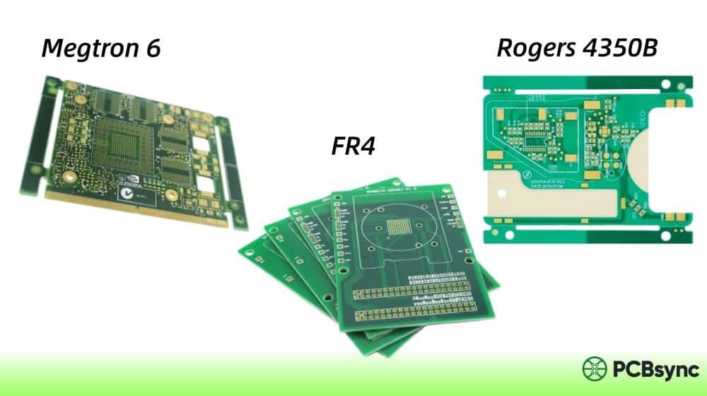
Choosing the right Rogers PCB material requires understanding how RO4500 compares to other options in the portfolio. Here’s how it stacks up against common alternatives.
RO4500 vs RO4350B
RO4350B is one of Rogers’ most popular high-frequency laminates, used extensively in RF power amplifiers, LNBs, and general microwave circuits.
Parameter
RO4500 Series
RO4350B
Dielectric Constant
3.3-3.5
3.48
Dk Tolerance
±0.08
±0.05
Dissipation Factor (10 GHz)
0.0025-0.0037
0.0037
Primary Application
Antenna elements
RF circuits, power amps
PIM Optimization
Yes
Standard
Cost
Lower
Higher
RO4350B offers tighter Dk tolerance (±0.05 vs ±0.08), which matters more in precision impedance matching applications. However, RO4500’s specific optimization for antenna applications—particularly PIM performance and dimensional stability—makes it the better choice for printed antenna designs.
RO4500 vs RO4003C
RO4003C is a halogen-free, environmentally-friendly alternative within the RO4000 family.
Parameter
RO4500 Series
RO4003C
Dielectric Constant
3.3-3.5
3.38
Dissipation Factor (10 GHz)
0.0025-0.0037
0.0027
Z-axis CTE
35-46 ppm/°C
46 ppm/°C
Target Application
Commercial antennas
General RF, lower loss priority
Halogen-Free Options
RO4533, RO4534
Yes
RO4003C has slightly lower loss (Df = 0.0027), making it attractive for applications where insertion loss is critical. However, RO4500’s superior dimensional stability and PIM characteristics give it the edge for antenna-specific applications.
RO4500 vs AD Series (AD250C, AD255C, AD300C)
The AD Series are PTFE-based antenna materials offering the lowest possible loss.
Parameter
RO4500 Series
AD Series
Base Material
Hydrocarbon ceramic
PTFE/glass
Dissipation Factor
0.0020-0.0037
0.0010-0.0018
Processing
FR-4 compatible
Requires special treatment
Cost
Lower
Higher
PIM Performance
< -155 dBc
< -157 dBc
The AD Series wins on electrical performance—lower loss and slightly better PIM. But the significant processing advantages of RO4500 often tip the balance for high-volume commercial applications where cost per unit matters.
RO4500 PCB Design Considerations
Getting the most out of RO4500 PCB material requires attention to a few key design factors. Here’s what I’ve learned from practical experience.
Dielectric Constant Selection for Impedance Control
When designing transmission lines or matching networks on RO4500, use the design Dk value rather than the process specification value. The design Dk accounts for typical copper foil effects and gives more accurate impedance predictions.
For RO4500 materials:
Manufacturing process Dk: 3.3-3.5 (depending on variant)
Design Dk (for impedance calculation): Typically 0.05-0.1 higher
Always verify impedance calculations against your fabricator’s process data and consider test coupons for critical designs.
LoPro Foil Considerations
RO4500 LoPro variants use a modified resin system to bond low-profile (LoPro) copper foil. This configuration offers:
Lower conductor loss at high frequencies
Improved PIM performance
Reduced etch factor for finer features
However, the LoPro resin adds approximately 0.0007″ (18 μm) to the core thickness for double-sided boards. The LoPro resin itself has a Dk of approximately 2.4, which affects the overall effective Dk—particularly noticeable on thinner cores. Factor this into your stack-up planning.
Thermal Management in High-Power Antennas
While RO4500’s thermal conductivity (0.6 W/m-K) is adequate for most antenna applications, high-power designs may need additional thermal consideration. Options include:
RO4500 laminates are available in large panel sizes (24″ x 18″ and 48″ x 36″ standard), which helps maximize yield for antenna arrays. The excellent dimensional stability (<0.05%) means you can confidently design close-tolerance features across large panels without excessive compensation.
Stack-up Design for Multilayer Antennas
When designing multilayer RO4500 PCB stack-ups, consider these practical guidelines:
Core and Prepreg Selection: RO4400 and RO4400T series bondplys are specifically designed for use with RO4500 cores. They provide matched thermal properties and compatible processing characteristics.
Hybrid Constructions: For cost optimization, consider hybrid stack-ups where RO4500 is used only for RF layers while standard FR-4 is used for DC distribution and mechanical support layers. This approach can significantly reduce material costs while maintaining RF performance where it matters.
Symmetrical Stack-ups: Always design symmetrical stack-ups to minimize warpage. This is particularly important for large antenna panels that must maintain flatness for proper radiation pattern performance.
Ground Plane Considerations: For microstrip antenna elements, ensure adequate ground plane coverage. The effective Dk of the material assumes a continuous ground reference—large ground cutouts can alter impedance and radiation characteristics.
RO4500 PCB Fabrication Guidelines
From a manufacturing perspective, RO4500 is one of the more forgiving high-frequency materials. Here are practical fabrication considerations.
Drilling and Hole Preparation
Use standard carbide drills; no special tooling required
Entry/backup material: Standard FR-4 compatible materials work well
Desmear: Conventional permanganate or plasma processes are effective
No sodium etch or special PTFE preparation needed
Copper Plating
The resin system provides good adhesion to electroless copper without special surface treatment. Standard direct metallization processes work effectively.
Etching
Standard alkaline etchants produce good results
Etch factor is comparable to FR-4
For fine-line features, the LoPro variants offer improved resolution due to lower foil profile
Lamination (Multilayer Builds)
RO4500 can be combined with other RO4000 series materials for multilayer constructions:
Compatible bondplys: RO4400, RO4400T series
Can be combined with FR-4 cores/prepregs for hybrid constructions
Standard high-temperature lamination cycles apply
Solder Assembly
Fully compatible with lead-free reflow profiles (peak temperatures up to 260°C)
For production antenna designs, implement these quality checks:
Incoming Material Inspection: Verify material certification matches your specifications. Check for physical defects like delamination, surface contamination, or dimensional issues.
Dk Verification Coupons: Include test coupons on production panels to verify dielectric constant. Resonant ring or split-post dielectric resonator methods can confirm Dk values.
PIM Testing: For base station antenna applications, final PIM testing is typically required. Ensure your test setup (frequency, power level, swept vs. spot testing) matches end-customer requirements.
Dimensional Verification: For antenna arrays, verify element spacing and overall panel dimensions. The excellent dimensional stability of RO4500 usually results in minimal deviation, but verification provides traceability.
Typical Applications for RO4500 PCB
RO4500 PCB materials find their primary home in commercial antenna applications where cost, performance, and manufacturability must balance.
Cellular Infrastructure Antennas
Base station antennas for 4G LTE and 5G networks represent the largest volume application. The combination of:
Consistent Dk for predictable antenna patterns
Low PIM for FDD system compatibility
FR-4 processability for volume production
Cost advantages over PTFE alternatives
…makes RO4500 a natural fit for this market.
WiMAX and Broadband Wireless Access
Fixed wireless systems use similar antenna architectures to cellular, making RO4500 equally applicable for these designs.
Small Cell and DAS Antennas
Distributed Antenna Systems (DAS) and small cell deployments benefit from RO4500’s combination of performance and cost—particularly important when deploying hundreds or thousands of antenna units.
Industrial Wireless and IoT
Industrial IoT applications with antenna requirements can leverage RO4500’s reliability and consistent performance for long-deployment scenarios.
Military and Defense Applications
While not the primary target market, RO4500 PCB materials are used in some defense antenna applications where cost-performance balance is prioritized over ultimate specifications. The material’s reliability and controlled properties make it suitable for:
UAV communication antennas
Ground-based communication systems
Non-critical radar applications
Training and simulation systems
For classified or mission-critical defense applications, higher-specification materials (like the AD Series or specialized PTFE laminates) may be required.
Automotive and V2X Communications
Vehicle-to-everything (V2X) communication systems require compact, reliable antennas. RO4500’s automotive qualification (temperature range, vibration resistance, and consistent performance) makes it suitable for:
Dedicated short-range communications (DSRC)
Cellular V2X (C-V2X) antennas
Telematics and connectivity modules
RO4500 Datasheet and Specifications Summary
For quick reference, here’s a consolidated specification summary for RO4500 PCB materials:
Property
RO4533
RO4534
RO4535
Unit
Electrical
Dielectric Constant (Dk) @10GHz
3.3
3.4
3.5
–
Dk Tolerance
±0.08
±0.08
±0.08
–
Dissipation Factor @2.5GHz
0.0020
0.0025
0.0037
–
Dissipation Factor @10GHz
0.0025
0.0030
0.0037
–
Volume Resistivity
1.7×10¹⁰
1.7×10¹⁰
4.2×10⁹
MΩ·cm
Surface Resistivity
4.6×10⁹
5.4×10⁹
1.3×10⁸
MΩ
Thermal
Glass Transition Temperature
>280
>280
>280
°C
CTE (X-axis)
13
13
14
ppm/°C
CTE (Y-axis)
11
12
12
ppm/°C
CTE (Z-axis)
37
35
46
ppm/°C
Thermal Conductivity
0.62
0.69
0.66
W/m-K
Mechanical
Flexural Strength (MD)
210
207
207
MPa
Dimensional Stability
<0.05
<0.05
<0.05
%
Density
1.96
1.88
2.06
g/cm³
Compliance
Halogen-Free
Yes
Yes
No
–
UL94 Rating
HB
HB
V-0
–
RoHS Compliant
Yes
Yes
Yes
–
How to Source RO4500 PCB Material
If you’re ready to specify RO4500 for your project, here are practical sourcing considerations.
Through PCB Fabricators
Most high-frequency PCB manufacturers stock or can readily obtain RO4500 materials. When requesting quotes:
Specify the exact variant (RO4533, RO4534, or RO4535)
Indicate if LoPro foil is required
Provide thickness requirements
Note any specific copper weight needs
Many fabricators offer Rogers materials as part of their standard high-frequency capabilities.
Direct from Distributors
Rogers materials are available through authorized distributors worldwide. For prototype quantities or material evaluation:
Contact Rogers Corporation directly for samples
Request small panel quantities through distribution
Obtain latest datasheets and design guides
Lead Time Considerations
Standard RO4500 variants typically have reasonable availability, but:
Non-standard thicknesses may have longer lead times
Large production quantities should be planned with adequate lead time
Consider buffer stock for critical production programs
Useful Resources for RO4500 PCB Design
Here are valuable resources for engineers working with RO4500 PCB materials:
PIM and PCB Antennas Guide: Technical guide covering PIM fundamentals and material selection
RO4000 Fabrication Guidelines: Processing recommendations for the RO4000 family
Rogers Technology Support Hub: Calculators, tools, and technical papers
Design Tools
Impedance Calculators: Rogers provides online impedance calculation tools accounting for their specific materials
Laminate Properties Tool: Interactive comparison of all Rogers high-frequency laminates
Stack-up Planning Tools: Available through most EDA software with Rogers material libraries
Sample Requests
Rogers offers sample materials for evaluation. Visit their website and navigate to the sample request section, providing your application details for fastest processing.
Frequently Asked Questions About RO4500 PCB
What is the dielectric constant of RO4500 PCB material?
RO4500 PCB materials have dielectric constants ranging from 3.3 to 3.5 (±0.08), depending on the specific variant. RO4533 has a Dk of 3.3, RO4534 has a Dk of 3.4, and RO4535 has a Dk of 3.5. These values are specified at 10 GHz in the z-direction. For impedance calculations, use the design Dk value, which is typically 0.05-0.1 higher than the process specification.
Is RO4500 compatible with standard FR-4 PCB processing?
Yes, RO4500 PCB materials are fully compatible with conventional FR-4 fabrication processes. Unlike PTFE-based laminates that require special sodium etching or plasma treatment for through-hole preparation, RO4500 can be processed using standard drilling, desmear, plating, and etching techniques. This compatibility significantly reduces manufacturing costs and expands the base of qualified fabricators.
What is the difference between RO4533, RO4534, and RO4535?
The three variants differ primarily in dielectric constant and compliance characteristics. RO4533 (Dk=3.3) and RO4534 (Dk=3.4) are halogen-free materials suitable for environmentally-conscious applications. RO4535 (Dk=3.5) incorporates flame retardant technology with UL94 V-0 certification for applications requiring fire safety compliance. RO4533 also has the lowest loss tangent (0.0020 at 2.5 GHz), making it optimal for lowest-loss antenna designs.
Can RO4500 PCB be used for 5G antenna applications?
Absolutely. RO4500 PCB materials are well-suited for 5G antenna applications, particularly in sub-6 GHz bands. The material’s low PIM performance (better than -155 dBc) is critical for 5G FDD deployments, and the controlled dielectric constant ensures consistent antenna performance across production. For millimeter-wave 5G applications (above 24 GHz), you may need to evaluate whether the loss characteristics meet your specific link budget requirements.
What is PIM, and why does it matter for RO4500 PCB antennas?
Passive Intermodulation (PIM) occurs when two or more high-power RF signals mix at nonlinear junctions, creating unwanted intermodulation products. In base station antennas, these products can fall into the receive band and degrade receiver sensitivity, reducing system capacity and increasing dropped calls. RO4500 PCB materials are specifically engineered to minimize PIM, achieving levels better than -155 dBc. This makes them suitable for demanding wireless infrastructure applications where PIM can significantly impact network performance.
Conclusion
RO4500 PCB materials occupy a valuable position in the high-frequency laminate landscape. They deliver the RF performance needed for commercial antenna applications while maintaining full compatibility with high-volume FR-4 manufacturing processes. For antenna designers working on cellular infrastructure, WiMAX, or other wireless systems, RO4500 offers an optimal balance of performance, cost, and manufacturability.
The key takeaways when considering RO4500 for your next project:
Choose the variant (RO4533/4534/4535) based on your Dk requirements and compliance needs
Leverage FR-4 compatible processing for lower costs and broader fab sourcing
Specify LoPro foil for demanding PIM or high-frequency applications
Use design Dk values for accurate impedance calculations
Work with fabricators experienced in Rogers materials for best results
Whether you’re designing a new base station antenna array or evaluating alternatives to your current substrate, RO4500 PCB deserves serious consideration as a cost-effective, high-performance solution.
Inquire: Call 0086-755-23203480, or reach out via the form below/your sales contact to discuss our design, manufacturing, and assembly capabilities.
Quote: Email your PCB files to Sales@pcbsync.com (Preferred for large files) or submit online. We will contact you promptly. Please ensure your email is correct.
Notes: For PCB fabrication, we require PCB design file in Gerber RS-274X format (most preferred), *.PCB/DDB (Protel, inform your program version) format or *.BRD (Eagle) format. For PCB assembly, we require PCB design file in above mentioned format, drilling file and BOM. Click to download BOM template To avoid file missing, please include all files into one folder and compress it into .zip or .rar format.


