Inquire: Call 0086-755-23203480, or reach out via the form below/your sales contact to discuss our design, manufacturing, and assembly capabilities.
Quote: Email your PCB files to Sales@pcbsync.com (Preferred for large files) or submit online. We will contact you promptly. Please ensure your email is correct.
Notes: For PCB fabrication, we require PCB design file in Gerber RS-274X format (most preferred), *.PCB/DDB (Protel, inform your program version) format or *.BRD (Eagle) format. For PCB assembly, we require PCB design file in above mentioned format, drilling file and BOM. Click to download BOM template To avoid file missing, please include all files into one folder and compress it into .zip or .rar format.
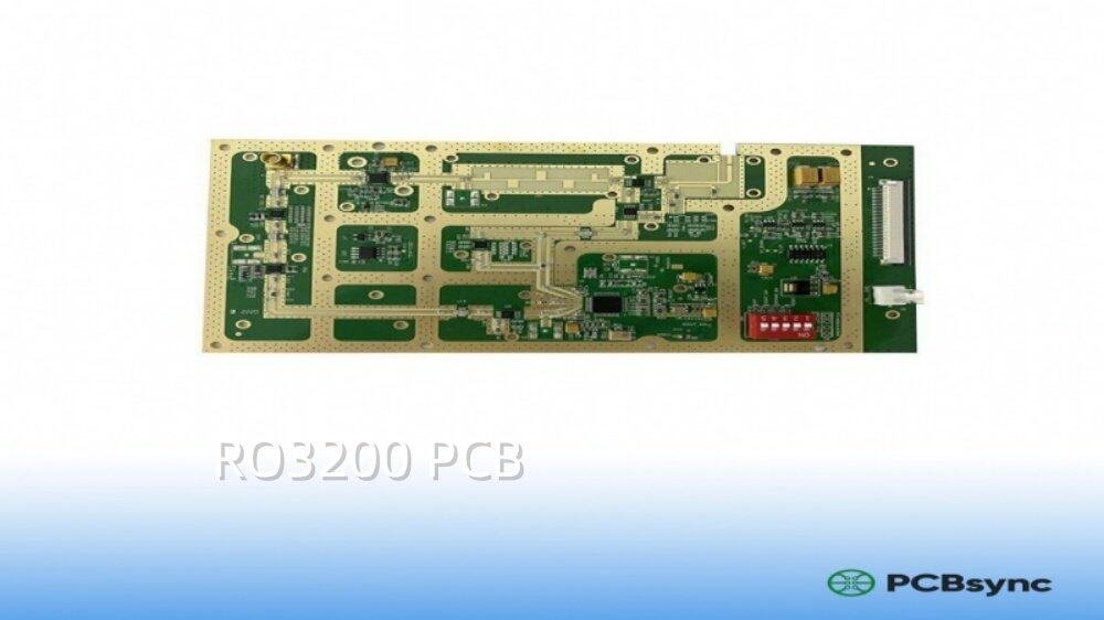
If you’ve been working on RF or microwave circuits and need something more mechanically robust than standard PTFE laminates, chances are you’ve come across the RO3200 series from Rogers Corporation. I’ve used these materials extensively in antenna designs and radar projects, and they’ve consistently delivered where other laminates fell short.
This guide covers everything you need to know about RO3200 PCB materials—from technical specifications to real-world fabrication tips. Whether you’re evaluating this material for your next project or troubleshooting an existing design, you’ll find practical, engineer-tested information here.
The demand for high-frequency PCB materials has exploded in recent years. With 5G networks rolling out globally, autonomous vehicles becoming reality, and satellite communications expanding, engineers need laminates that perform reliably at frequencies that were once considered exotic. The RO3200 series addresses these challenges head-on, offering the electrical properties needed for modern RF designs while solving many of the fabrication headaches that plague other PTFE-based materials.
RO3200 PCB refers to printed circuit boards manufactured using Rogers Corporation’s RO3200 series laminates. These are ceramic-filled PTFE composites reinforced with woven fiberglass, designed specifically for high-frequency applications where both electrical performance and mechanical stability matter.
The RO3200 series sits within the broader RO3000 family but distinguishes itself through one critical feature: woven glass reinforcement. This reinforcement provides significantly better dimensional stability compared to the non-reinforced RO3000 materials, making RO3200 PCB an excellent choice for applications requiring tight tolerances and reliable multilayer constructions.
Rogers developed the RO3200 series to bridge the gap between the excellent electrical properties of pure PTFE materials and the mechanical robustness needed for practical manufacturing. The result is a laminate that handles like a more conventional material while still delivering the low-loss performance that microwave designers demand.
The ceramic filler used in RO3200 PCB materials serves multiple purposes. It adjusts the dielectric constant to specific target values, improves thermal conductivity compared to unfilled PTFE, and enhances dimensional stability. The woven glass reinforcement adds mechanical strength without significantly compromising electrical performance—a balance that took considerable material science expertise to achieve.
All RO3200 series materials are manufactured under an ISO 9002 certified quality system, ensuring consistent properties from batch to batch. This consistency is critical when you’re designing circuits where small variations in dielectric constant can shift filter frequencies or change antenna patterns.
RO3200 Series Variants
The RO3200 family includes three distinct materials, each optimized for different dielectric constant requirements:
Variant
Dielectric Constant (Dk)
Dissipation Factor (Df)
Target Applications
RO3203
3.02
0.0016
Extended frequency range beyond 40 GHz
RO3206
6.15
0.0027
Miniaturized circuits, GPS antennas
RO3210
10.2
0.0027
Maximum miniaturization, phased arrays
Each variant maintains the same mechanical properties, which is a significant advantage when designing multilayer boards that combine different dielectric layers. You can mix RO3203, RO3206, and RO3210 in a single stackup without worrying about warpage or CTE mismatch issues.
Technical Specifications of RO3200 PCB
Understanding the detailed specifications of RO3200 PCB materials is essential for making informed design decisions. Here’s what the numbers actually mean for your projects.
Electrical Properties
The electrical characteristics of RO3200 PCB materials make them suitable for demanding RF and microwave applications. Understanding these properties helps you make informed design trade-offs.
The dielectric constant (Dk) determines how much the material slows down electromagnetic waves compared to free space. Higher Dk materials allow smaller physical dimensions for a given electrical length—useful for miniaturization but potentially at the cost of increased losses. The RO3200 series offers Dk values from 3.02 to 10.2, giving designers significant flexibility.
The low dissipation factor of RO3203 (0.0016) stands out in this lineup. This value extends the practical operating frequency well beyond 40 GHz, making RO3203 particularly valuable for 5G mmWave and automotive radar applications operating at 77 GHz.
Thermal Properties
Thermal behavior directly impacts reliability in high-power applications and environments with temperature cycling.
Property
Value
Unit
Significance
CTE (X-axis)
11
ppm/°C
Matches well with copper
CTE (Y-axis)
14
ppm/°C
Good dimensional stability
CTE (Z-axis)
35
ppm/°C
Critical for PTH reliability
Thermal Conductivity
0.50
W/m·K
Better than standard FR-4
Td (Decomposition Temperature)
500
°C
High thermal stability
The coefficient of thermal expansion (CTE) values deserve attention. The X and Y axis CTEs of 11 and 14 ppm/°C respectively are reasonably close to copper’s 17 ppm/°C, which helps maintain dimensional stability during thermal cycling. The Z-axis CTE of 35 ppm/°C, while higher, is still manageable for plated through-hole reliability.
Mechanical Properties
The woven glass reinforcement in RO3200 PCB provides significantly improved mechanical characteristics compared to non-reinforced PTFE materials.
Property
Value
Unit
Test Method
Tensile Modulus (X-axis)
20,684
MPa
IPC-TM-650 2.4.19
Tensile Modulus (Y-axis)
18,615
MPa
IPC-TM-650 2.4.19
Peel Strength (1 oz Cu)
1.05
N/mm
IPC-TM-650 2.4.8
Flexural Strength
193
MPa
IPC-TM-650 2.4.4
Water Absorption
0.02
%
IPC-TM-650 2.6.2
That 0.02% water absorption figure is excellent. Low moisture uptake means the dielectric properties remain stable in humid environments—a real concern for outdoor installations and automotive applications.Read more Rogers PCBs:
RO3200 vs RO3000: Understanding the Key Differences
Engineers often ask whether they should use RO3200 or the standard RO3000 series. The decision comes down to mechanical requirements and fabrication considerations.
Mechanical Stability Comparison
The primary advantage of RO3200 PCB over RO3000 lies in its woven glass reinforcement. This reinforcement provides:
Better dimensional stability: Critical for tight-tolerance designs and fine-pitch components
Improved handling: Less prone to creep and deformation during fabrication
Higher rigidity: Better suited for applications requiring structural integrity
Surface smoothness: Enables finer line etching tolerances despite the glass reinforcement
For Rogers PCB materials in general, the RO3200 series offers a practical middle ground between the superior electrical properties of pure PTFE and the mechanical robustness needed for reliable manufacturing.
When to Choose RO3200 Over RO3000
Based on my experience, here are the scenarios where RO3200 makes more sense:
Choose RO3200 when:
Your design requires multilayer construction with mixed dielectric layers
The PCB will undergo significant thermal cycling
You need consistent dimensional stability across multiple fabrication runs
The application involves mechanical stress or vibration
Maximum electrical performance is the only priority
Single-layer or simple double-sided designs
Cost is a primary concern
The application operates in a controlled, stable environment
Applications of RO3200 PCB
The combination of excellent high-frequency performance and mechanical stability makes RO3200 PCB suitable for a wide range of demanding applications.
Automotive Radar Systems
RO3200 PCB materials have found extensive use in automotive collision avoidance and ADAS (Advanced Driver Assistance Systems) applications. The 77 GHz automotive radar frequency band demands materials with:
Stable Dk across temperature variations encountered in vehicles
Good mechanical properties for withstanding vibration and thermal cycling
Consistent batch-to-batch properties for high-volume manufacturing
The RO3203 variant, with its low Df of 0.0016, is particularly well-suited for these applications. Its frequency capability extending beyond 40 GHz provides adequate margin for 77 GHz radar designs.
Modern automotive radar systems use multiple sensors around the vehicle—front-facing long-range radar for adaptive cruise control, corner radars for blind spot detection, and short-range sensors for parking assistance. Each sensor relies on PCB antennas that must perform consistently across the temperature extremes encountered in automotive environments, from cold winter mornings to hot summer parking lots. RO3200 materials deliver this reliability.
The trend toward higher-resolution imaging radar, which requires more antenna elements and tighter phase control, has increased demands on PCB material consistency. RO3200’s stable properties support the precise phase relationships needed for accurate angle estimation and object classification.
5G Wireless Infrastructure
The rollout of 5G networks, particularly in mmWave bands (28 GHz, 39 GHz, and beyond), has increased demand for high-frequency PCB materials. RO3200 PCB supports:
Massive MIMO antenna arrays requiring consistent phase performance
Base station power amplifiers where thermal stability matters
Backhaul equipment operating at microwave frequencies
Small cell deployments where size and performance must balance
The ability to maintain consistent electrical properties across different dielectric constants makes RO3200 valuable for complex multilayer designs common in 5G infrastructure.
One particular challenge in 5G mmWave systems is the need for antenna arrays with large numbers of elements. A typical 5G base station antenna might contain 64, 128, or even 256 individual radiating elements, each fed by a network of transmission lines on the PCB. Any variation in the dielectric constant across the board translates directly to phase errors that degrade beam-forming performance. RO3200’s tight Dk tolerances help manage this challenge.
The thermal requirements of 5G equipment also favor RO3200 materials. Power amplifiers for mmWave frequencies operate at elevated temperatures, and the PCB must maintain stable properties throughout the operating range. The ceramic filler in RO3200 contributes to better thermal conductivity than unfilled PTFE, helping to spread heat away from active devices.
Antenna Systems
From patch antennas to phased array systems, RO3200 PCB materials deliver the performance needed for modern antenna designs.
Application
Preferred Variant
Key Benefit
GPS/GNSS Antennas
RO3206/RO3210
Size reduction through higher Dk
Microstrip Patch Antennas
RO3203
Low loss at operating frequency
Phased Array Systems
RO3203/RO3206
Consistent properties in multilayer
Satellite Communications
RO3203
Extended frequency range
Additional High-Frequency Applications
RO3200 PCB materials also serve well in:
Power amplifiers: The thermal stability supports high-power operation
Communication systems: Both terrestrial and satellite links
Remote meter reading: Low-power RF systems
Data link systems: Cable and fiber distribution networks
Base station infrastructure: Front-end and backhaul components
PCB Fabrication Guidelines for RO3200
Working with RO3200 PCB materials requires attention to specific processing parameters. Here’s what fabricators and designers need to know. While the material is more forgiving than pure PTFE laminates, ignoring these guidelines can lead to quality problems that affect both yield and long-term reliability.
Material Preparation
Before any processing begins, proper material preparation is essential. RO3200 laminates should be allowed to acclimate to the fabrication environment for at least 24 hours before processing. This prevents moisture-related issues during high-temperature operations like lamination and soldering.
For inner layer processing in multilayer constructions, bake the material at 150°C (300°F) for 2-4 hours before lamination. This drives out any absorbed moisture that could cause delamination or blistering during the lamination cycle.
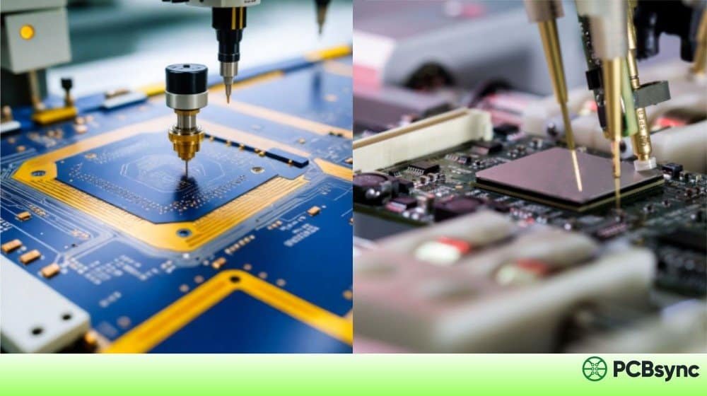
Drilling Parameters
Proper drilling is critical for maintaining hole quality and PTH reliability.
Parameter
Recommended Value
Entry Material
Aluminum or rigid entry board
Exit Material
Standard backup board
Stack Height
2-3 panels maximum
Surface Speed
150-200 SFM
Chip Load
0.002-0.003 inches/revolution
Retract Rate
Standard or slightly reduced
Use sharp carbide drill bits and replace them more frequently than you would for FR-4. The ceramic filler in RO3200 is abrasive and will wear tooling faster.
Lamination Process
For multilayer RO3200 PCB constructions, follow these guidelines:
Temperature: 375-400°F (190-204°C)
Pressure: 200-350 PSI
Dwell Time: 60-90 minutes at temperature
Cooldown Rate: 3-5°F per minute
When combining RO3200 with other materials in hybrid stackups, verify CTE compatibility to avoid warpage. RO3200 works well with epoxy-based materials like FR-4 in mixed constructions.
Copper Etching Considerations
The smooth surface of RO3200 PCB materials enables finer line etching tolerances compared to many other high-frequency laminates. Key points:
Standard alkaline etchants work well
Rinse thoroughly immediately after etching
Avoid prolonged exposure to etching chemicals
The smooth surface permits trace widths down to 3-4 mils with proper process control
Storage and Handling
RO3200 laminates should be stored in a controlled environment:
Temperature: 60-80°F (15-27°C)
Humidity: 40-60% RH
Keep material in original packaging until use
Handle with clean, lint-free gloves
Avoid bending or flexing panels
Design Considerations for RO3200 PCB
Beyond material selection and fabrication, successful RO3200 PCB designs require attention to several factors. Good design practices can help you extract maximum performance from this high-quality material.
Transmission Line Design
RO3200 materials work well with various transmission line structures. The choice between microstrip, stripline, and grounded coplanar waveguide (GCPW) depends on your frequency range and isolation requirements.
For microstrip designs on RO3200, keep these points in mind:
The smooth surface enables fine conductor geometries
Use the design Dk value provided by Rogers, not the measured process value
Account for conductor thickness effects on impedance at narrow trace widths
Consider edge-coupled designs for filter and coupler implementations
Impedance Control
The stable dielectric constant of RO3200 materials makes impedance control more predictable than with FR-4. However, you should:
Account for the specific Dk of your chosen variant
Use manufacturer-provided design Dk values, which account for typical production variation
Consider the frequency-dependent behavior of Dk for mmWave designs
Verify trace dimensions with your fabricator before finalizing layouts
Multilayer Stackup Design
The consistent mechanical properties across RO3200 variants enable sophisticated multilayer designs:
Use different Dk layers for impedance optimization without warpage concerns
Consider RO3200 for RF layers combined with FR-4 for digital/power layers
Maintain symmetric stackups to minimize bow and twist
Account for glass weave effects at higher frequencies
Thermal Management
For high-power RO3200 PCB applications:
Incorporate thermal vias in power amplifier areas
Use copper pours for heat spreading
Consider the 0.50 W/m·K thermal conductivity when sizing thermal features
Account for the relatively low thermal conductivity compared to metal-core alternatives
Advantages and Limitations of RO3200 PCB
Every material involves trade-offs. Here’s an honest assessment of RO3200 based on real-world project experience.
Advantages
Understanding the strengths of RO3200 PCB helps you leverage them effectively in your designs:
Excellent high-frequency performance: Low loss extends usefulness to 40+ GHz, making it suitable for automotive radar and 5G mmWave applications
Mechanical stability: Woven glass reinforcement improves handling and reliability compared to non-reinforced PTFE materials
Consistent properties: Same mechanical characteristics across all Dk variants, simplifying multilayer design
Multilayer compatibility: Works well in mixed-material stackups with FR-4 and other epoxy-based materials
Surface quality: Smooth surface enables fine-line etching, supporting trace widths down to 3-4 mils
Low moisture absorption: 0.02% water absorption ensures stable performance in humid environments
Proven track record: Established material with extensive industry adoption and well-documented processing guidelines
Temperature stability: Dielectric properties remain stable across a wide temperature range
Limitations
Being aware of limitations helps you design around them or select alternative materials when appropriate:
Higher cost: More expensive than standard FR-4 or lower-tier high-frequency materials, typically 5-10x the price of FR-4 per square foot
Special processing: Requires attention to fabrication parameters; not all fabricators have experience with PTFE-based materials
Lead times: May have longer availability than commodity materials, especially for unusual thickness/copper combinations
Tooling wear: Ceramic filler is abrasive to drilling equipment, requiring more frequent bit replacement
Thermal conductivity: At 0.50 W/m·K, lower than metal-core alternatives for high-power applications where heat dissipation is critical
Not suitable for all frequencies: For applications below 1 GHz, the performance advantages over FR-4 may not justify the cost
Specialized bonding: Multilayer constructions may require specific prepreg materials for optimal results
Cost Considerations
RO3200 PCB materials command a premium over FR-4, but the price is justified for applications that require their performance characteristics. When evaluating cost:
Compare total system cost, not just material cost
Consider reliability implications of using less capable materials
Factor in potential redesign costs if initial material choice proves inadequate
Evaluate hybrid constructions that use RO3200 only where needed
How to Choose the Right RO3200 Variant
Selecting between RO3203, RO3206, and RO3210 depends on your specific requirements.
Decision Matrix
If You Need…
Choose…
Because…
Lowest possible loss
RO3203
Df of 0.0016 is best in class
Maximum size reduction
RO3210
Dk of 10.2 allows smallest features
Balanced performance
RO3206
Good compromise of size and loss
Frequencies above 30 GHz
RO3203
Extended frequency capability
GPS or GNSS antennas
RO3206/RO3210
Higher Dk suits miniaturized designs
Phased array antennas
RO3203
Low loss critical for array efficiency
Application-Based Selection
For automotive radar (77 GHz)
Primary choice: RO3203
Rationale: Lowest Df extends performance to mmWave frequencies
For 5G mmWave (28/39 GHz)
Primary choice: RO3203 or RO3206
Rationale: Depends on size constraints versus loss budget
For satellite communications (Ku/Ka band)
Primary choice: RO3203
Rationale: Low loss critical for link budget
For handheld device antennas
Primary choice: RO3206 or RO3210
Rationale: Size reduction outweighs modest increase in loss
Useful Resources for RO3200 PCB
Here are the official resources that will help you work with RO3200 materials:
Official Datasheets and Guides
Resource
Description
Where to Find
RO3200 Series Data Sheet
Complete specifications for all variants
Rogers Corporation website
Fabrication Guidelines
Detailed processing instructions
Rogers ACS document library
Quick Reference Processing Guidelines
Condensed fabrication tips
Rogers technical resources
Laminate Properties Tool
Interactive material comparison
Rogers online tools
Design Support Hub
Technical papers and calculators
Rogers tech hub portal
Download Links
RO3200 Series Data Sheet (PDF): Available at rogerscorp.com under Advanced Electronics Solutions > RO3000 Series > RO3200 Series Laminates
Fabrication Guidelines: Search for “Fabrication Guidelines RO3000 and RO3200 Series High Frequency Circuit Materials”
Material Safety Data Sheets: Available in multiple languages from Rogers document library
Additional Support
Technology Support Hub: Technical papers, white papers, calculators
Sample Request: Free samples available through Rogers online request system
Sales Engineers: Local representatives available for application support
Bonding Material Properties Tool: For selecting compatible prepregs
Frequently Asked Questions About RO3200 PCB
What is the maximum operating frequency for RO3200 PCB materials?
RO3203 offers the best high-frequency performance in the RO3200 series, with a useful frequency range extending beyond 40 GHz. This makes it suitable for automotive radar at 77 GHz and 5G mmWave applications. RO3206 and RO3210 are rated for use beyond 20 GHz. The actual maximum depends on your loss budget and specific design requirements.
Can RO3200 be combined with FR-4 in a multilayer PCB?
Yes, RO3200 PCB materials work well in hybrid constructions with FR-4 and other epoxy-based materials. The key is to maintain a symmetric stackup and account for CTE differences during thermal cycling. Many designs use RO3200 for RF-critical layers and FR-4 for power distribution and digital signal layers, reducing overall cost while maintaining high-frequency performance where it matters.
What is the difference between RO3200 and RO4000 series?
Both series are high-frequency materials from Rogers, but they differ in composition and processing. RO3200 uses ceramic-filled PTFE with woven glass reinforcement, while RO4000 uses hydrocarbon ceramic laminates. RO4000 is often easier to process using standard FR-4 techniques, while RO3200 offers better high-frequency performance, particularly at mmWave frequencies. The choice depends on your frequency requirements and fabrication capabilities.
How does RO3200 handle temperature variations in automotive applications?
RO3200 materials are designed for the thermal demands of automotive environments. The decomposition temperature (Td) of 500°C provides a large margin above operating temperatures. More importantly, the dielectric constant remains stable across the temperature range typically encountered in vehicles (-40°C to +125°C). The CTE characteristics also support reliable plated through-hole connections through repeated thermal cycling.
What standard thicknesses are available for RO3200 PCB laminates?
Conclusion
RO3200 PCB materials offer a compelling combination of high-frequency electrical performance and mechanical stability that many applications demand. The woven glass reinforcement addresses the handling and dimensional stability challenges of pure PTFE materials while maintaining the low-loss characteristics needed for RF and microwave circuits.
Whether you’re designing automotive radar systems, 5G infrastructure, or satellite communication equipment, the RO3200 series provides options across a range of dielectric constants to optimize your design. The key is matching the specific variant—RO3203, RO3206, or RO3210—to your application’s requirements for loss, size, and frequency of operation.
For your next high-frequency project, consider working with an experienced fabricator familiar with RO3200 processing requirements. The material performs exceptionally well when handled correctly, delivering the reliability and performance that demanding applications require.
Inquire: Call 0086-755-23203480, or reach out via the form below/your sales contact to discuss our design, manufacturing, and assembly capabilities.
Quote: Email your PCB files to Sales@pcbsync.com (Preferred for large files) or submit online. We will contact you promptly. Please ensure your email is correct.
Notes: For PCB fabrication, we require PCB design file in Gerber RS-274X format (most preferred), *.PCB/DDB (Protel, inform your program version) format or *.BRD (Eagle) format. For PCB assembly, we require PCB design file in above mentioned format, drilling file and BOM. Click to download BOM template To avoid file missing, please include all files into one folder and compress it into .zip or .rar format.


