Inquire: Call 0086-755-23203480, or reach out via the form below/your sales contact to discuss our design, manufacturing, and assembly capabilities.
Quote: Email your PCB files to Sales@pcbsync.com (Preferred for large files) or submit online. We will contact you promptly. Please ensure your email is correct.
Notes: For PCB fabrication, we require PCB design file in Gerber RS-274X format (most preferred), *.PCB/DDB (Protel, inform your program version) format or *.BRD (Eagle) format. For PCB assembly, we require PCB design file in above mentioned format, drilling file and BOM. Click to download BOM template To avoid file missing, please include all files into one folder and compress it into .zip or .rar format.
If you’ve been designing RF circuits for automotive radar, 5G antennas, or satellite communications, you’ve probably come across Rogers materials. Among them, RO3010 PCB stands out as one of the most versatile high-frequency laminates available today. With its unique combination of high dielectric constant, low loss, and excellent dimensional stability, RO3010 has become a go-to choice for engineers working on compact, high-performance microwave circuits.
In this guide, I’ll walk you through everything you need to know about RO3010 PCB—from its material properties and real-world applications to fabrication tips that can save you headaches during manufacturing. Whether you’re evaluating RO3010 for your next project or looking to optimize your existing designs, this comprehensive resource has you covered.
RO3010 is a ceramic-filled PTFE (Polytetrafluoroethylene) composite laminate manufactured by Rogers Corporation. It belongs to the RO3000 series, which is specifically engineered for commercial microwave and RF applications. What makes RO3010 unique within this family is its high dielectric constant (Dk) of 10.2—the highest in the RO3000 series.
This high Dk value isn’t just a number on a datasheet. It directly translates to shorter wavelengths at any given frequency, which means you can design more compact circuits without sacrificing performance. For applications where board real estate is at a premium—think automotive radar modules or handheld communication devices—this characteristic is invaluable.
The material consists of a PTFE matrix filled with ceramic particles, which gives it exceptional thermal stability and mechanical properties. Unlike pure PTFE materials that can be soft and difficult to handle, the ceramic filling in RO3010 provides the rigidity needed for reliable PCB fabrication while maintaining the excellent electrical properties that PTFE is known for.
Understanding the RO3000 Series Family
To fully appreciate RO3010 PCB, it helps to understand where it fits within the broader RO3000 product family. Rogers designed this series to offer different dielectric constants while maintaining consistent mechanical properties across all variants:
RO3003: Dk of 3.0 – lowest loss, largest circuit dimensions
RO3035: Dk of 3.5 – balanced option for moderate miniaturization
RO3006: Dk of 6.15 – mid-range dielectric constant
RO3010: Dk of 10.2 – maximum miniaturization potential
This consistency in mechanical properties is a significant engineering advantage. You can design multilayer boards using different dielectric constants for different layers without worrying about warpage, delamination, or reliability issues that would occur with mismatched materials. This flexibility opens up sophisticated design possibilities for complex RF systems.
Key Properties and Specifications of RO3010 PCB
Understanding the technical specifications of RO3010 is crucial for making informed design decisions. Let me break down the key parameters that matter most for RF and microwave applications.
Electrical Properties
The electrical characteristics of RO3010 are what set it apart from conventional PCB materials and even other high-frequency laminates.
The dielectric constant of 10.2 is measured using the clamped stripline method per IPC-TM-650. However, when you’re doing RF simulations, you’ll want to use the “Design Dk” value of 11.20, which accounts for real-world operating conditions across a broader frequency range (8-40 GHz).
One of the most impressive aspects of RO3010 is its Dk stability. Unlike FR-4, which shows significant Dk variation with both temperature and frequency, RO3010 maintains consistent electrical properties. This stability is crucial for applications like band-pass filters, voltage-controlled oscillators, and phased array antennas where even small variations in dielectric constant can cause performance degradation or system failures.
The thermal coefficient of dielectric constant (TCDk) for RO3010 is among the lowest available in high-Dk materials. This means your carefully tuned RF circuits will perform predictably whether operating in a freezing warehouse or a sun-baked vehicle dashboard.
The dissipation factor of 0.0022 at 10 GHz is impressively low, meaning signal attenuation through RO3010 PCB remains minimal even at millimeter-wave frequencies. This low loss characteristic enables the material to perform reliably in applications up to 77 GHz—covering everything from 5G communications to automotive radar systems.
Thermal Properties
Thermal stability is where RO3010 really shines compared to standard FR-4 or even some other PTFE-based materials.
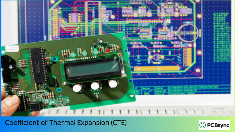
The CTE values deserve special attention. Notice how the X and Y axis CTEs (13 and 11 ppm/°C) are remarkably close to copper’s CTE of approximately 17 ppm/°C. This matched expansion coefficient is a game-changer for reliability—it minimizes thermal stress between the copper traces and the laminate during temperature cycling, reducing the risk of trace delamination and via failures.
The thermal conductivity of 0.62-0.79 W/m·K is significantly better than standard FR-4 (typically 0.1-0.5 W/m·K), making RO3010 PCB suitable for power amplifier applications where heat dissipation is critical.
Mechanical Properties
Property
Value
Test Method
Peel Strength
9.4 lb/in
After solder float
Flexural Strength
>16,000 psi
–
Water Absorption
0.05%
D24/23
Flammability
V-0
UL 94
The extremely low water absorption rate of 0.05% means RO3010 PCB maintains consistent electrical performance even in humid environments. This is particularly important for outdoor applications like GPS antennas or satellite communication systems that may be exposed to varying environmental conditions.
The unique property combination of RO3010 makes it suitable for a wide range of high-frequency applications. Let me walk you through the most common use cases I’ve encountered.
Automotive Radar Systems
This is probably the fastest-growing application segment for RO3010 PCB. Modern vehicles use 77 GHz radar systems for advanced driver assistance systems (ADAS) including:
Adaptive cruise control
Blind spot detection
Collision avoidance systems
Parking assistance
Lane change assist
Cross-traffic alert
Pedestrian detection
At 77 GHz, the wavelength is only about 4mm in free space, which shrinks to roughly 1.2mm inside RO3010 due to its high dielectric constant. This enables extremely compact antenna arrays that can be seamlessly integrated into vehicle bumpers and grilles.
The automotive industry has stringent reliability requirements. Vehicles must operate reliably across a temperature range of -40°C to +85°C (and often higher for under-hood applications). RO3010’s stable Dk over temperature ensures that the radar’s phase accuracy and detection performance remain consistent whether you’re driving in Death Valley or Alaska.
The material’s matched CTE with copper is particularly important here—automotive radar modules undergo thousands of temperature cycles during a vehicle’s lifetime. Mismatched expansion coefficients would lead to solder joint failures, trace cracks, and via reliability issues. RO3010’s CTE characteristics help ensure these modules last the life of the vehicle.
Modern automotive radar systems also use MIMO (Multiple Input Multiple Output) configurations with phased array antennas. These complex antenna structures demand precise phase control across multiple elements, which requires a material with uniform dielectric properties—another area where RO3010 excels.
5G and Telecommunications
The rollout of 5G networks has created enormous demand for high-frequency PCB materials. RO3010 PCB finds applications in:
Base station antennas and power amplifiers
Small cell units
Massive MIMO antenna arrays
Phased array antenna systems
RF filters and couplers
The ability to miniaturize circuits using RO3010’s high Dk is particularly valuable for 5G small cells, where equipment must be compact enough for mounting on lamp posts and building facades.
Satellite and Aerospace Communications
Aerospace applications demand materials that can withstand extreme conditions while maintaining consistent RF performance. RO3010 is used in:
Direct broadcast satellite (DBS) low-noise block downconverters
GPS antenna systems
Satellite communication terminals
Airborne radar systems
Electronic warfare systems
The material’s low outgassing characteristics (important for space applications) and excellent thermal stability make it suitable for these demanding environments.
Patch Antennas and RF Modules
The high dielectric constant of RO3010 makes it ideal for microstrip patch antennas where size reduction is critical. A patch antenna designed on RO3010 will be approximately 70% smaller than an equivalent antenna on FR-4, while offering superior efficiency due to lower dielectric losses.
Common RF module applications include:
Voltage-controlled oscillators (VCOs)
Band-pass filters
Power amplifiers
Low-noise amplifiers (LNAs)
RF mixers and couplers
RO3010 vs Other Rogers Materials
Choosing the right Rogers PCB material can be confusing given the many options available. Here’s how RO3010 compares to other popular choices.
RO4350B is often the first choice for many RF designs because it can be processed using standard FR-4 fabrication techniques. However, when circuit miniaturization is essential or when you need the absolute lowest loss at frequencies above 30 GHz, RO3010 PCB is the superior choice.
RO3003 offers the lowest loss in the RO3000 series but requires larger circuit dimensions due to its lower Dk. The choice between these materials often comes down to whether miniaturization or loss performance is your primary design driver.
RO3010 vs FR-4
Parameter
RO3010
Standard FR-4
Dielectric Constant (Dk)
10.2
4.2-4.8
Dissipation Factor (Df)
0.0022
0.02
Dk Stability
Excellent
Poor above 1 GHz
Thermal Conductivity
0.62-0.79 W/m·K
0.1-0.5 W/m·K
Cost
10-20x higher
Baseline
Maximum Frequency
77+ GHz
~1-2 GHz practical
FR-4 simply cannot compete with RO3010 at frequencies above a few GHz. The dielectric constant of FR-4 varies significantly with frequency and temperature, making precise impedance control impossible. For any serious RF design above 500 MHz, specialized materials like RO3010 are essential.
RO3010 PCB Fabrication Guidelines
Fabricating RO3010 PCB requires some modifications to standard PTFE processing techniques. Here’s what you and your PCB manufacturer need to know.
Material Handling and Storage
PTFE-based materials like RO3010 are softer than FR-4 and require careful handling:
Store material flat in a clean, dry environment
Avoid folding or creasing the laminate
Use lint-free gloves when handling
Pre-bake before processing to remove absorbed moisture (typically 2-4 hours at 150°C)
Drilling Considerations
The ceramic-filled PTFE construction affects drilling parameters:
Parameter
Recommendation
Drill Speed
200-300 SFM
Feed Rate
1.5-3.0 mils/rev
Retraction Rate
500-1000 IPM
Stack Height
2-3 panels maximum
Use carbide drills with positive rake angles. Diamond-coated drills can extend tool life significantly when drilling high volumes of RO3010 PCB.
Plasma Treatment
Before plating, RO3010 requires plasma treatment to prepare the PTFE surface for metallization:
Plasma desmear is essential for reliable plated through-holes
Use CF4/O2 or similar fluorine-containing plasma chemistry
Typical treatment time: 10-20 minutes depending on equipment
This step is critical—skip it, and you’ll likely experience plating adhesion failures.
Etching
Standard alkaline or cupric chloride etchants work well with RO3010, but you should:
Use milder etchant concentrations to prevent over-etching
Reduce exposure times compared to FR-4
Monitor etch factor carefully for fine-pitch designs
Lamination for Multilayer Designs
RO3010 can be combined with other materials in multilayer stackups:
RO3010 + FR-4 hybrid constructions are common for cost optimization
Use RO3000 series bondply for homogeneous multilayer boards
The material’s consistent mechanical properties regardless of Dk value make it compatible with other RO3000 series materials in mixed-dielectric multilayer designs.
Design Tips for RO3010 PCB
Drawing from practical experience, here are some design guidelines that can help you get the most out of RO3010.
Understanding Wavelength Compression
Before diving into specific tips, it’s important to understand why RO3010’s high Dk matters for your designs. The wavelength inside any dielectric material is related to the free-space wavelength by:
λ_material = λ_free-space / √Dk
For RO3010 with Dk = 10.2, this means wavelengths inside the material are approximately 31% of free-space wavelengths. At 77 GHz (where free-space λ ≈ 3.9mm), the wavelength inside RO3010 is only about 1.2mm. This compression enables dramatic size reduction but also means tolerances become more critical.
Impedance Control
The high Dk of RO3010 means trace widths for a given impedance will be narrower than on lower-Dk materials:
For 50Ω microstrip on 10 mil RO3010: trace width ≈ 5-6 mils
Always include test coupons for impedance verification
Account for copper foil roughness in calculations (use Ra value from datasheet)
Consider using Rogers’ MWI (Microwave Impedance) calculator for accurate modeling
The narrow trace widths required for 50Ω impedance on RO3010 can be challenging for PCB fabricators. Work closely with your manufacturer to ensure they can achieve the required tolerances, and consider specifying a slightly higher impedance (like 55Ω) if it allows for more manufacturable trace widths without significantly impacting your design.
Transmission Line Structures
Different transmission line structures have different advantages on RO3010 PCB:
Microstrip: Simplest to fabricate, good for most applications. The high Dk reduces radiation losses at millimeter-wave frequencies.
Grounded Coplanar Waveguide (GCPW): Offers better isolation and is often preferred for 77 GHz automotive radar. Provides excellent ground return paths and reduces crosstalk.
Stripline: Best for applications requiring shielding from external interference. Requires multilayer construction but offers the most consistent impedance.
Thermal Management
Despite good thermal conductivity, high-power designs still need attention:
Use thermal via arrays under power devices
Consider copper coin inserts for extreme thermal loads
Calculate power dissipation carefully—RO3010’s Td of 500°C provides headroom, but junction temperatures matter
The compact circuit sizes enabled by RO3010 can concentrate heat in smaller areas—plan your thermal strategy early
Via Design
Via performance is critical at high frequencies:
Keep via aspect ratios below 8:1 for reliable plating
Use back-drilling to remove via stubs in thick multilayer boards
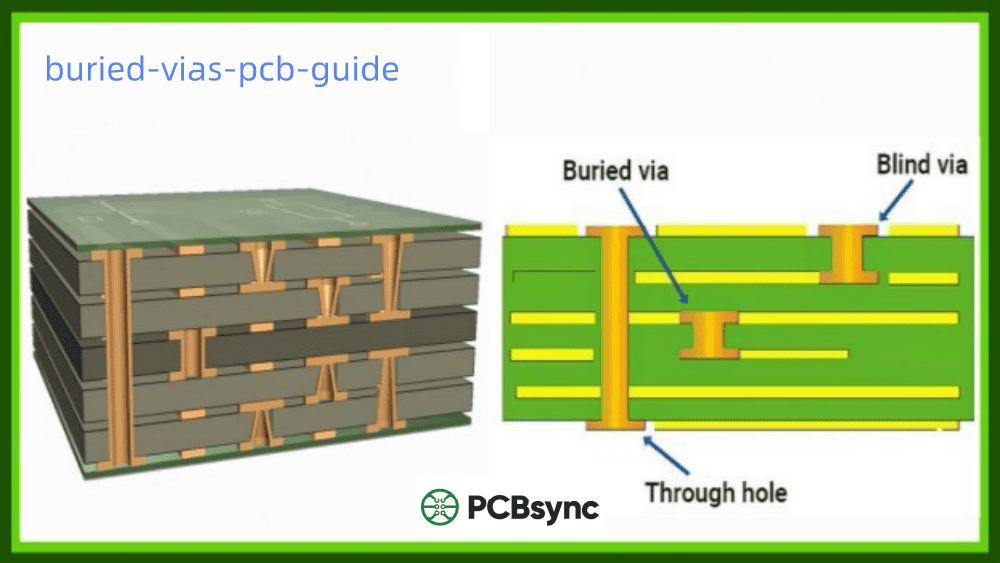
Consider blind/buried vias for complex RF routing
Minimize via inductance in ground return paths
Ground Plane Design
Proper grounding is essential for RO3010 PCB performance:
Use solid ground planes without excessive cutouts
Provide adequate via stitching around RF traces
Consider coplanar waveguide (CPW) structures for better isolation
Ensure continuous ground reference under all transmission lines
Available Thicknesses and Configurations
RO3010 is available in several standard configurations to suit different design requirements.
Standard Thicknesses
Thickness
Tolerance
0.005″ (0.13 mm)
± 0.0005″
0.010″ (0.25 mm)
± 0.0007″
0.025″ (0.64 mm)
± 0.0010″
0.050″ (1.28 mm)
± 0.0020″
Panel Sizes
12″ × 18″ (305 × 457 mm)
24″ × 18″ (610 × 457 mm)
24″ × 36″ (610 × 915 mm)
Copper Cladding Options
0.5 oz (17 µm)
1 oz (35 µm)
2 oz (70 µm)
Both electrodeposited and rolled copper foils are available, with rolled copper offering better performance at high frequencies due to smoother surface characteristics.
Cost Considerations
Let’s be honest—RO3010 isn’t cheap. Expect to pay significantly more than standard FR-4, with prices typically ranging from $100-600 per sheet depending on thickness, copper weight, and panel size.
Cost Optimization Strategies
Hybrid Stackups: Use RO3010 only on RF signal layers; use FR-4 or lower-cost materials for power and ground planes
Panel Utilization: Optimize your design for efficient panel nesting
Volume Negotiations: Work with your supplier on pricing for production quantities
Alternative Materials: For less demanding applications, consider RO4350B which offers good RF performance at lower cost
When the Cost Is Justified
The premium price of RO3010 PCB is justified when:
Circuit miniaturization is a primary requirement
Operating frequencies exceed 30 GHz
Temperature stability is critical
Long-term reliability in harsh environments is essential
The application demands the lowest possible insertion loss
Advantages and Limitations of RO3010 PCB
Advantages
Highest Dk in RO3000 series enables maximum circuit miniaturization
RO3010 can be reliably used in applications up to 77 GHz and beyond. The material’s low dissipation factor and stable dielectric constant make it suitable for millimeter-wave frequencies commonly used in automotive radar (77 GHz), 5G mmWave (24-39 GHz), and satellite communications. The practical frequency limit depends more on your design and manufacturing capabilities than the material itself.
Is RO3010 compatible with lead-free soldering?
Yes, RO3010 is fully compatible with lead-free soldering processes. With a decomposition temperature (Td) of 500°C, the material can easily withstand the higher temperatures required for lead-free solder reflow (typically 245-260°C peak). The material also meets RoHS compliance requirements and carries a UL 94 V-0 flammability rating.
Can RO3010 be used in multilayer PCB designs?
Absolutely. RO3010 is well-suited for multilayer constructions and can be combined with other RO3000 series materials using Rogers bondply. It’s also commonly used in hybrid stackups with FR-4 or other laminates, where RO3010 is used for RF signal layers while lower-cost materials handle power distribution. The consistent mechanical properties across the RO3000 series prevent warpage issues in mixed-dielectric designs.
How does RO3010 compare to Taconic or Isola high-frequency materials?
RO3010 competes with materials like Taconic RF-10 and Isola Astra MT77 in the high-Dk laminate space. While each has its merits, RO3010 is generally preferred for its proven track record, extensive application data, and wide availability. The choice often comes down to specific application requirements, existing supplier relationships, and regional availability. For new designs, the extensive documentation and design support available for Rogers materials often tips the decision in favor of RO3010.
What is the typical lead time for RO3010 PCB fabrication?
Lead times vary significantly based on complexity and manufacturer. For prototypes, expect 2-4 weeks from a specialized RF PCB manufacturer. Production quantities may require 4-8 weeks depending on volume. It’s worth noting that fewer PCB shops have experience with PTFE materials, so plan accordingly and establish relationships with qualified suppliers before your project timeline becomes critical.
Conclusion
RO3010 PCB represents one of the most capable high-frequency laminate materials available today. Its unique combination of high dielectric constant, low loss, and excellent thermal stability makes it the material of choice for applications demanding compact, high-performance microwave circuits.
While the material does require specialized fabrication techniques and commands a premium price, these trade-offs are often worthwhile for applications in automotive radar, 5G telecommunications, satellite communications, and aerospace systems. Understanding the material’s properties and design considerations covered in this guide will help you make the most of RO3010 in your next RF project.
Making the Right Material Choice
The decision to use RO3010 PCB should be driven by your specific application requirements:
Choose RO3010 when:
Circuit miniaturization is a primary design goal
Operating frequencies are above 30 GHz
Temperature stability over a wide range is critical
You need the highest possible Dk in the RO3000 family
Long-term reliability in harsh environments is essential
Consider alternatives when:
Cost is the primary constraint
Standard FR-4 processing compatibility is required
Operating frequencies are below 10 GHz
Circuit size is not a limiting factor
If you’re working on a design that pushes frequency boundaries or demands maximum miniaturization, RO3010 deserves serious consideration. Partner with an experienced RF PCB manufacturer who understands PTFE processing, and you’ll be well-positioned to take advantage of everything this exceptional material has to offer.
The future looks bright for RO3010 applications. As automotive radar systems become standard equipment, 5G networks continue their rollout, and satellite internet constellations expand, demand for reliable, high-performance RF circuits will only grow. Materials like RO3010 will play a crucial role in enabling the next generation of wireless technology.
Inquire: Call 0086-755-23203480, or reach out via the form below/your sales contact to discuss our design, manufacturing, and assembly capabilities.
Quote: Email your PCB files to Sales@pcbsync.com (Preferred for large files) or submit online. We will contact you promptly. Please ensure your email is correct.
Notes: For PCB fabrication, we require PCB design file in Gerber RS-274X format (most preferred), *.PCB/DDB (Protel, inform your program version) format or *.BRD (Eagle) format. For PCB assembly, we require PCB design file in above mentioned format, drilling file and BOM. Click to download BOM template To avoid file missing, please include all files into one folder and compress it into .zip or .rar format.


