Inquire: Call 0086-755-23203480, or reach out via the form below/your sales contact to discuss our design, manufacturing, and assembly capabilities.
Quote: Email your PCB files to Sales@pcbsync.com (Preferred for large files) or submit online. We will contact you promptly. Please ensure your email is correct.
Notes: For PCB fabrication, we require PCB design file in Gerber RS-274X format (most preferred), *.PCB/DDB (Protel, inform your program version) format or *.BRD (Eagle) format. For PCB assembly, we require PCB design file in above mentioned format, drilling file and BOM. Click to download BOM template To avoid file missing, please include all files into one folder and compress it into .zip or .rar format.
Gerber File Extensions from Different Software: A Complete PCB Engineer’s Guide
If you’ve ever exported Gerber files from your PCB design software and wondered why the file extensions look completely different from your colleague’s files, you’re not alone. Understanding Gerber file extensions from different software is one of those practical skills that separates experienced PCB engineers from beginners. After years of working with various CAD tools and dealing with fabrication houses, I’ve learned that knowing these extensions inside-out can save you countless hours of troubleshooting and prevent costly manufacturing delays.
What Are Gerber Files and Why Do Extensions Matter?
Gerber files serve as the universal language between PCB designers and manufacturers. They’re essentially 2D vector images that describe every layer of your printed circuit board, from copper traces to solder masks to silkscreen markings. The format was originally developed by Gerber Scientific in the 1960s and has since become the de facto industry standard.
Here’s where things get interesting: while the Gerber format itself is standardized, the file extensions that different CAD software packages use are anything but standardized. Each software vendor has developed their own naming conventions, which means the same layer (let’s say, your top copper layer) could be named .GTL in Altium, .TOP in PADS, or F.Cu.gbr in KiCad.
This matters because when you send your files to a PCB manufacturer, their CAM engineers need to identify each layer correctly. Misidentified layers can lead to reversed boards, incorrect solder masks, or even completely unusable PCBs. Trust me, I’ve seen it happen, and it’s never a fun conversation with your project manager.
Understanding Gerber Format Versions
Before diving into specific software extensions, let’s quickly cover the Gerber format versions you’ll encounter.
RS-274-D (Standard Gerber)
This is the original format, and frankly, you should avoid it whenever possible. RS-274-D requires a separate aperture file to define the shapes used in your design, which creates additional complexity and potential for errors. Most modern manufacturers won’t even accept RS-274-D files anymore.
RS-274-X (Extended Gerber)
This format, also known as Gerber X1, embeds aperture definitions directly within the file. It’s self-contained, widely supported, and should be your go-to format for most fabrication jobs. When someone mentions “Gerber files” without specifying a version, they usually mean RS-274-X.
Gerber X2 and X3
Released in 2014 and 2020 respectively, these newer formats add metadata attributes that help manufacturers automatically identify layer functions, component information, and other details. Gerber X2 is backward compatible with RS-274-X, so there’s no downside to using it if your software supports it.
Gerber File Extensions from Major PCB Design Software
Now let’s get into the meat of this guide. Below is a comprehensive breakdown of Gerber file extensions generated by the most popular PCB design software packages.
Altium Designer / Protel Extensions
Altium Designer (and its predecessor Protel) uses what’s often called the “Protel naming convention,” which has become something of an informal industry standard. Many manufacturers prefer receiving files with these extensions because they’re instantly recognizable.
Layer Type
Extension
Description
Top Copper
.GTL
Gerber Top Layer
Bottom Copper
.GBL
Gerber Bottom Layer
Inner Layer 1
.G1
First inner copper layer
Inner Layer 2
.G2
Second inner copper layer
Top Solder Mask
.GTS
Gerber Top Solder mask
Bottom Solder Mask
.GBS
Gerber Bottom Solder mask
Top Silkscreen
.GTO
Gerber Top Overlay
Bottom Silkscreen
.GBO
Gerber Bottom Overlay
Top Paste
.GTP
Gerber Top Paste mask
Bottom Paste
.GBP
Gerber Bottom Paste mask
Board Outline
.GKO / .GM1
Keep-out or Mechanical layer
Drill File
.TXT / .DRL
Excellon NC drill data
The logic behind Altium’s naming is actually quite intuitive once you understand it: “G” for Gerber, “T” or “B” for Top or Bottom, and then a letter indicating the layer type (L for Layer/copper, S for Solder mask, O for Overlay/silkscreen, P for Paste).
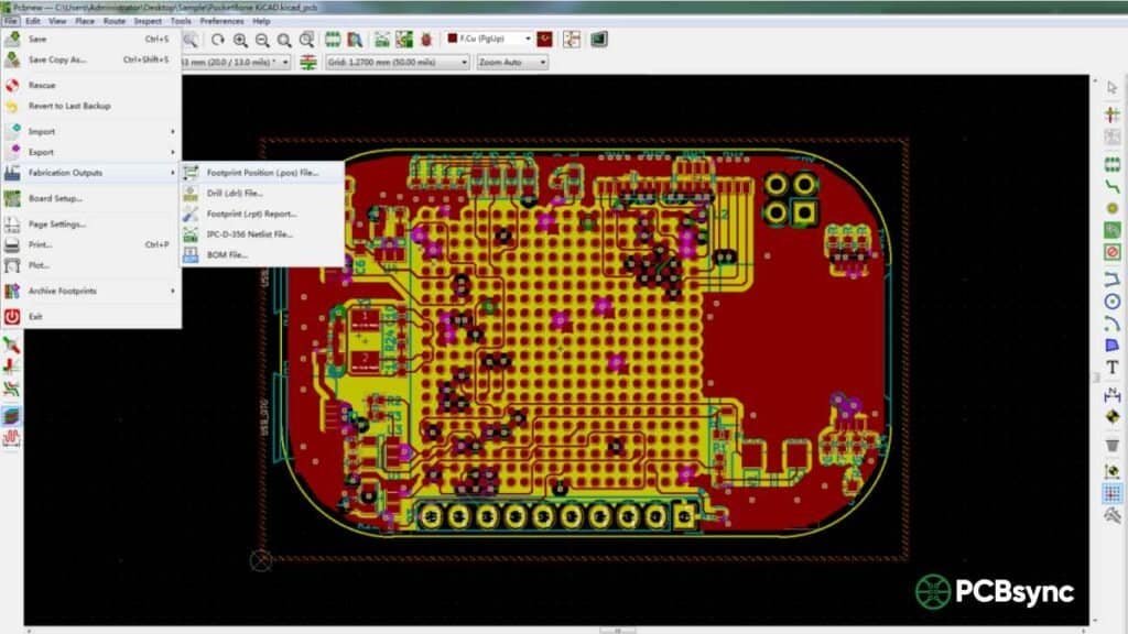
KiCad Extensions
KiCad, being open-source, takes a more descriptive approach to file naming. This can be helpful for beginners but sometimes causes confusion with automated systems at fabrication houses.
Layer Type
Extension
Description
Top Copper
-F_Cu.gbr
Front Copper
Bottom Copper
-B_Cu.gbr
Back Copper
Inner Layer 1
-In1_Cu.gbr
Inner Layer 1 Copper
Inner Layer 2
-In2_Cu.gbr
Inner Layer 2 Copper
Top Solder Mask
-F_Mask.gbr
Front Mask
Bottom Solder Mask
-B_Mask.gbr
Back Mask
Top Silkscreen
-F_SilkS.gbr
Front Silkscreen
Bottom Silkscreen
-B_SilkS.gbr
Back Silkscreen
Top Paste
-F_Paste.gbr
Front Paste
Bottom Paste
-B_Paste.gbr
Back Paste
Board Outline
-Edge_Cuts.gbr
Edge Cuts layer
Drill File
.drl
Excellon drill file
KiCad also offers an option to use “Protel filenames,” which generates extensions compatible with the Altium convention. I generally recommend enabling this option when submitting files to manufacturers, as it reduces the chance of layer identification errors.
Autodesk EAGLE Extensions
EAGLE uses a slightly different convention that reflects its origin as a simpler, more accessible PCB tool.
Layer Type
Extension
Description
Top Copper
.CMP / .TOP
Component side copper
Bottom Copper
.SOL / .BOT
Solder side copper
Inner Layer 2
.LY2
Layer 2
Inner Layer 3
.LY3
Layer 3
Top Solder Mask
.STC / .TSM
Top Solder mask
Bottom Solder Mask
.STS / .BSM
Bottom Solder mask
Top Silkscreen
.PLC / .TSK
Top Silkscreen
Bottom Silkscreen
.PLS / .BSK
Bottom Silkscreen
Top Paste
.CRC / .TSP
Top Paste
Bottom Paste
.CRS / .BSP
Bottom Paste
Board Outline
.DIM / .MIL / .GML
Dimension/Milling layer
Drill File
.DRD / .XLN
Drill data
EAGLE’s CAM processor is quite flexible, allowing you to customize output extensions. If you’re working with EAGLE, I’d suggest setting up a CAM job that outputs Protel-compatible extensions for easier manufacturer communication.
Cadence OrCAD Extensions
OrCAD tends to use a more verbose naming approach with .art or .PHO extensions.
Layer Type
Extension
Description
Top Copper
TOP.art / L1.PHO
Top signal layer
Bottom Copper
BOTTOM.art / L2.PHO
Bottom signal layer
Inner Layers
IN1.art / L3.PHO
Inner layer artwork
Top Solder Mask
SOLDERTOP.art / MT.PHO
Top mask
Bottom Solder Mask
SOLDERBOT.art / MB.PHO
Bottom mask
Top Silkscreen
SILKTOP.art / ST.PHO
Top silkscreen
Bottom Silkscreen
SILKBOT.art / SB.PHO
Bottom silkscreen
Top Paste
PASTETOP.art / PT.PHO
Top paste
Bottom Paste
PASTEBOT.art / PB.PHO
Bottom paste
Board Outline
OUTLINE.art
Board outline
Drill File
.TAP / .DRL
Drill file
Many fabricators request that OrCAD users rename their files to follow the Protel convention before submission, as the .art and .PHO extensions aren’t automatically recognized by some CAM systems.
Mentor PADS Extensions
PADS uses yet another naming scheme that can sometimes confuse automated layer detection systems.
Layer Type
Extension
Description
Top Copper
.TOP
Top copper
Bottom Copper
.BOT
Bottom copper
Inner Signal
.IN1, .IN2
Inner signal layers
Inner Plane
.GP1, .GP2
Internal plane layers
Top Solder Mask
.SMT
Solder mask top
Bottom Solder Mask
.SMB
Solder mask bottom
Top Silkscreen
.SST
Silkscreen top
Bottom Silkscreen
.SSB
Silkscreen bottom
Top Paste
.SPT
Solder paste top
Bottom Paste
.SPB
Solder paste bottom
Board Outline
.FAB
Fabrication outline
Drill File
.DRL
Drill data
Best Practices for Managing Gerber File Extensions
After dealing with hundreds of PCB designs, here are my recommendations for avoiding extension-related headaches:
Always Include a README File
Include a simple text file in your Gerber package that maps each file to its layer function. This takes five minutes and can save days of back-and-forth with your manufacturer.
Verify Before You Submit
Use a Gerber viewer to load all your files and visually confirm that each layer displays correctly. This simple step catches most extension-related issues before they become problems.
Stick to One Convention When Possible
If your organization uses multiple CAD tools, consider standardizing on the Protel naming convention for all Gerber exports. Most software packages support this as an output option.
Communicate with Your Manufacturer
Different fabrication houses have different preferences. Some have automated systems that work better with certain extensions. A quick email asking about their preferred format can prevent issues down the line.
Useful Resources and Tools
Here are some valuable resources for working with Gerber files:
The official Gerber format specification is maintained by Ucamco and is freely available. You can download the complete specification at https://www.ucamco.com/gerber to understand exactly what’s inside these files.
Common Gerber Extension Mistakes to Avoid
Through my experience, these are the most common extension-related errors I’ve encountered:
Mixing Conventions
Don’t mix naming conventions in the same project. If you start with Protel extensions, stick with them throughout. Mixed naming confuses both automated systems and human reviewers.
Forgetting the Drill File
The drill file (usually .TXT, .DRL, or .XLN) isn’t technically a Gerber file, but it’s essential for manufacturing. Make sure it’s included and uses compatible coordinate settings with your Gerber files.
Incorrect Board Outline Extension
The board outline is critical for defining your PCB’s physical shape. Different software uses different default extensions (.GKO, .GM1, .Edge_Cuts), and missing or misnamed outline files are a common cause of fabrication delays.
Frequently Asked Questions
What is the standard Gerber file extension?
The official standard extension for Gerber files is .GBR or .gbr. However, in practice, most PCB design software uses layer-specific extensions like .GTL (top copper), .GBL (bottom copper), .GTS (top solder mask), etc., which are based on the Protel/Altium naming convention. These descriptive extensions help manufacturers quickly identify each layer’s function without needing to open the files.
Can I rename Gerber files to different extensions?
Yes, you can safely rename Gerber files because the file extension doesn’t change the actual data inside the file. However, be careful to maintain a clear mapping of which file corresponds to which layer. Always include documentation when submitting renamed files to your manufacturer, and verify the renamed files still open correctly in a Gerber viewer before submission.
Why do different PCB software use different Gerber extensions?
Each PCB design software developer created their own naming conventions before any industry-wide standard was established. While the Gerber format itself is standardized, the file naming conventions evolved independently within each software ecosystem. The Protel convention has become the most widely recognized, which is why many other software packages now offer it as an export option.
How do I know if my Gerber files are RS-274X or RS-274D format?
Open any of your Gerber files in a text editor. RS-274X files contain embedded aperture definitions that start with %ADD commands near the beginning of the file. RS-274D files lack these definitions and require a separate aperture file. Additionally, RS-274X files typically include extended commands starting with % symbols throughout the file, while RS-274D files contain only basic coordinate and draw commands.
Which Gerber file extension should I use for the board outline?
For the board outline, the most commonly accepted extensions are .GKO (Gerber Keep-Out, from Altium/Protel), .GM1 (Gerber Mechanical 1), or software-specific names like -Edge_Cuts.gbr (KiCad) and .DIM or .GML (EAGLE). The key is ensuring your manufacturer knows which file contains the board outline. When in doubt, use .GKO as it’s the most universally recognized extension for board outlines.
Conclusion
Understanding Gerber file extensions from different software might seem like a minor detail in PCB design, but it’s one of those foundational skills that makes the entire manufacturing process smoother. Whether you’re using Altium, KiCad, EAGLE, OrCAD, or PADS, knowing how each tool names its output files helps you communicate more effectively with manufacturers and catch potential issues before they become expensive problems.
The PCB industry has evolved significantly, and while we’re still dealing with multiple naming conventions, the trend is moving toward more standardized approaches like Gerber X2 with its embedded metadata. Until full standardization arrives, keep this guide handy, always verify your files in a viewer before submission, and maintain clear documentation of your layer mappings. Your future self (and your manufacturer’s CAM engineers) will thank you.
Inquire: Call 0086-755-23203480, or reach out via the form below/your sales contact to discuss our design, manufacturing, and assembly capabilities.
Quote: Email your PCB files to Sales@pcbsync.com (Preferred for large files) or submit online. We will contact you promptly. Please ensure your email is correct.
Notes: For PCB fabrication, we require PCB design file in Gerber RS-274X format (most preferred), *.PCB/DDB (Protel, inform your program version) format or *.BRD (Eagle) format. For PCB assembly, we require PCB design file in above mentioned format, drilling file and BOM. Click to download BOM template To avoid file missing, please include all files into one folder and compress it into .zip or .rar format.


