Inquire: Call 0086-755-23203480, or reach out via the form below/your sales contact to discuss our design, manufacturing, and assembly capabilities.
Quote: Email your PCB files to Sales@pcbsync.com (Preferred for large files) or submit online. We will contact you promptly. Please ensure your email is correct.
Notes: For PCB fabrication, we require PCB design file in Gerber RS-274X format (most preferred), *.PCB/DDB (Protel, inform your program version) format or *.BRD (Eagle) format. For PCB assembly, we require PCB design file in above mentioned format, drilling file and BOM. Click to download BOM template To avoid file missing, please include all files into one folder and compress it into .zip or .rar format.
If you’ve ever designed a 77 GHz automotive radar board or wrestled with signal loss on a 5G mmWave antenna, you know that material selection can make or break your project. After working with dozens of high-frequency laminates over the years, I keep coming back to one material that consistently delivers: the RO3003 PCB.
Rogers Corporation’s RO3003 laminate has become something of an industry standard for millimeter-wave applications. But understanding why it works so well—and when to use it—requires digging into the technical details. This guide covers everything you need to know about RO3003, from raw specifications to practical design considerations.
RO3003 is a ceramic-filled PTFE (polytetrafluoroethylene) composite laminate developed by Rogers Corporation specifically for high-frequency printed circuit board applications. Unlike standard FR-4 or even basic PTFE materials, RO3003 uses a unique ceramic filler system that delivers exceptional dielectric stability across wide temperature and frequency ranges.
The material belongs to the RO3000 series, which includes RO3003, RO3006, RO3010, and RO3035—each offering different dielectric constants while maintaining consistent mechanical properties. This consistency matters when you’re building multilayer boards that mix different Dk materials.
Why Engineers Choose RO3003
The primary reason RO3003 PCB has gained such traction in the industry comes down to one thing: predictability. When you’re designing circuits that operate at 77 GHz, even small variations in dielectric constant can throw off your impedance calculations and ruin antenna patterns. RO3003 eliminates the “step change” in Dk that occurs near room temperature with traditional PTFE-glass materials, giving you consistent performance regardless of operating conditions.
Another practical advantage? RO3003 doesn’t use glass cloth reinforcement, which eliminates the glass weave effect that can cause local Dk variations in your transmission lines. This becomes critical when trace widths shrink at millimeter-wave frequencies.
RO3003 PCB Specifications and Technical Properties
Before selecting any laminate, you need to understand its electrical, thermal, and mechanical characteristics. Here’s a comprehensive breakdown of RO3003 specifications based on Rogers Corporation’s published data.
The 0.0010 dissipation factor at 10 GHz is particularly impressive. This ultra-low loss tangent means minimal signal attenuation, which becomes crucial as frequencies increase into the millimeter-wave band.
Thermal and Mechanical Properties
Property
Value
Direction
Test Method
CTE (X/Y axis)
17 ppm/°C
In-plane
IPC-TM-650 2.4.41
CTE (Z axis)
24 ppm/°C
Through-plane
IPC-TM-650 2.4.41
Thermal Conductivity
0.50 W/m/K
–
ASTM C518
Decomposition Temperature (Td)
>500°C
–
ASTM D3850
Density
2.1 g/cm³
–
ASTM D792
Moisture Absorption
<0.04%
D48/50
IPC-TM-650 2.6.2
Copper Peel Strength
12.7 lb/in (1 oz after solder float)
–
IPC-TM-650 2.4.8
The CTE match between RO3003 (17 ppm/°C) and copper (~17 ppm/°C) ensures excellent dimensional stability during temperature cycling. This directly translates to reliable plated through-holes and minimal warpage in multilayer constructions.
Available Thickness and Cladding Options
RO3003 PCB material comes in several standard configurations to accommodate various design requirements:
Standard Thickness
Copper Cladding Options
0.005″ (0.13 mm)
¼ oz (9 µm) electrodeposited
0.010″ (0.25 mm)
½ oz (17 µm) electrodeposited
0.020″ (0.50 mm)
1 oz (35 µm) electrodeposited
0.030″ (0.75 mm)
2 oz (70 µm) electrodeposited
0.060″ (1.52 mm)
½ oz (17 µm) reverse treated
1 oz (35 µm) reverse treated
Standard panel sizes are 12″ × 18″ (305 × 457 mm) and 24″ × 18″ (610 × 457 mm). If you need custom sizes or thicknesses, contact Rogers or your PCB manufacturer—they can often accommodate special requests.
Key Benefits of Using RO3003 in High-Frequency PCB Design
What makes RO3003 PCB stand out from other high-frequency materials? Let me break down the practical advantages based on real-world design experience.
Ultra-Low Dielectric Loss
With a dissipation factor of just 0.0010 at 10 GHz, RO3003 provides some of the lowest insertion loss available in commercial-grade laminates. This matters tremendously when you’re dealing with:
Long transmission lines where losses accumulate
Antenna feed networks where every dB counts
Millimeter-wave frequencies where conductor and dielectric losses increase
For 77 GHz automotive radar applications, the low loss characteristic directly affects detection range. A radar system built on RO3003 can detect objects at greater distances compared to one using higher-loss materials.
Exceptional Dk Stability
The ±0.04 tolerance on dielectric constant might seem like a small detail, but consider what happens when you’re calculating impedance for a 50Ω microstrip line at 77 GHz. Your trace width might be 0.15 mm or less. A 5% variation in Dk can shift your impedance by several ohms, causing reflections and signal degradation.
RO3003’s Dk remains stable across:
Frequency range (consistent from 8-40 GHz)
Temperature (-50°C to +150°C)
Different production lots
This consistency simplifies design—you can trust your simulation results will match fabricated boards.
No Glass Weave Effect
Traditional PTFE-glass laminates use woven glass cloth for mechanical reinforcement. The problem? Glass and PTFE have different dielectric constants, creating periodic variations in effective Dk as traces cross over glass fibers.
RO3003 uses ceramic fillers instead of glass reinforcement, eliminating this issue entirely. Your transmission line impedance stays uniform along its entire length, which is especially important for:
Phased array antennas with tight phase matching requirements
High-order filters with narrow bandwidth
Precision couplers and power dividers
Cost-Effective for Volume Manufacturing
Compared to other ultra-low-loss materials like RT/duroid 5880, RO3003 offers a better price-performance ratio for most applications. The ceramic-filled PTFE composition provides excellent RF performance while being more economical than pure PTFE alternatives.
Rogers designed the RO3000 series specifically for volume manufacturing, meaning consistent availability and reasonable lead times—something that can’t be said for all specialty laminates.
RO3003 PCB Applications
Where does RO3003 PCB really shine? Based on industry adoption and design experience, here are the primary application areas.
Automotive Radar Systems (77 GHz)
This is arguably the killer application for RO3003. Modern vehicles use 77 GHz radar for:
Forward collision warning
Adaptive cruise control
Blind spot detection
Lane change assist
Parking assistance
The material’s combination of low loss, stable Dk, and good thermal performance makes it ideal for automotive environments where temperatures can swing from -40°C to +85°C. The absence of glass weave also helps maintain consistent antenna patterns critical for accurate object detection.
5G mmWave Infrastructure
5G networks operating in the 28 GHz, 39 GHz, and higher bands require antenna arrays with dozens or hundreds of elements. RO3003 PCB material provides:
Low insertion loss for efficient power distribution
Consistent phase characteristics across the array
Thermal stability for outdoor base stations
Many 5G antenna designers use RO3003 for the antenna layer while combining with lower-cost materials in the feeding network layers through hybrid stackups.
GPS and Satellite Antennas
Global positioning systems operate at L1 (1575.42 MHz), L2 (1227.60 MHz), and L5 (1176.45 MHz) frequencies. While these frequencies are lower than automotive radar, GPS antennas benefit from RO3003’s:
Low loss for improved receiver sensitivity
Stable Dk for accurate phase center location
Environmental stability for outdoor operation
Direct broadcast satellite (DBS) systems and satellite communication terminals also commonly use RO3003 for similar reasons.
Wireless Communication Systems
Power amplifiers and antenna systems in cellular base stations, point-to-point backhaul links, and wireless networking equipment frequently incorporate RO3003 PCB material. The laminate handles high power densities well while maintaining signal integrity.
Aerospace and Defense
Cost-sensitive aerospace applications benefit from RO3003’s balance of performance and price. Common uses include:
Radar systems
Electronic warfare
Communication systems
Guidance systems
For applications requiring tighter specifications, the newer RO3003G2 variant offers enhanced insertion loss performance with optimized resin and filler content.
Medical Devices
High-frequency medical imaging and diagnostic equipment increasingly rely on RO3003 PCB material. Applications include:
MRI gradient coils and RF systems
Ultrasonic imaging arrays
Wireless patient monitoring devices
Surgical navigation systems
The material’s biocompatibility (when properly encapsulated) and consistent electrical properties support the stringent reliability requirements of medical electronics.
Industrial Sensing and IoT
Remote meter reading, industrial automation, and IoT sensor networks operating at microwave frequencies use RO3003 for:
Level sensors and radar gauges
Motion detection systems
Wireless industrial communications
High-precision measurement equipment
The laminate’s low moisture absorption (<0.04%) ensures stable performance in industrial environments with varying humidity levels.
RO3003 vs. Other High-Frequency PCB Materials
Choosing the right laminate often means comparing multiple options. Here’s how RO3003 stacks up against common alternatives.
RO3003 vs. RO4003C Comparison
Parameter
RO3003
RO4003C
Dielectric Constant
3.00
3.38
Dissipation Factor
0.0010 @ 10 GHz
0.0027 @ 10 GHz
Material Type
Ceramic-filled PTFE
Thermoset hydrocarbon/ceramic
Processing
Standard PTFE techniques
Standard FR-4 techniques
Glass Reinforcement
No
Yes (woven glass)
Maximum Frequency
77+ GHz
~40 GHz practical limit
Relative Cost
Higher
Lower
When to choose RO3003: Ultra-low loss requirements, frequencies above 40 GHz, applications where glass weave effect causes problems.
When to choose RO4003C: Lower frequencies (<40 GHz), cost-sensitive applications, when standard FR-4 processing is required.
RO3003 vs. RT/duroid 5880
Parameter
RO3003
RT/duroid 5880
Dielectric Constant
3.00
2.20
Dissipation Factor
0.0010 @ 10 GHz
0.0009 @ 10 GHz
Thermal Conductivity
0.50 W/m/K
0.20 W/m/K
Maximum Frequency
77+ GHz
90+ GHz
Relative Cost
Moderate
Higher
RT/duroid 5880 offers slightly lower loss and a lower Dk, which can be advantageous for certain antenna designs requiring thicker substrates or higher impedance lines. However, RO3003’s better thermal conductivity makes it preferable for power handling applications.
RO3003 vs. Standard FR-4
Parameter
RO3003
Standard FR-4
Dielectric Constant
3.00
~4.5
Dissipation Factor
0.0010 @ 10 GHz
0.020+ @ 10 GHz
Dk Stability
±0.04
±0.3 (varies with frequency)
Maximum Frequency
77+ GHz
<2 GHz (practical)
Relative Cost
10-20×
1× (baseline)
FR-4 should never be used for RF applications above a few GHz. The high loss and Dk variability make it unsuitable for anything requiring signal integrity at microwave frequencies.
Design Guidelines for RO3003 PCB
Successfully implementing RO3003 requires understanding both the material’s capabilities and its quirks. Here are practical design considerations.
Stackup Recommendations
For simple 2-layer RF boards, a straightforward RO3003 core with copper on both sides works well. The typical stackup looks like:
Top Copper: 0.5-1 ozRO3003 Dielectric: 0.020″ or 0.030″Bottom Copper: 0.5-1 oz
For multilayer designs, RO3003 can be combined with:
RO3003 bonding film: For all-PTFE constructions
RO4450F bondply: For hybrid designs with RO4000 series materials
FR-4 prepreg: For mixed-material stackups (use only for non-critical layers)
When mixing materials, pay attention to CTE mismatches that can cause warpage during thermal cycling.
Trace Width and Impedance Control
At millimeter-wave frequencies, trace widths become very narrow. For a 50Ω microstrip on 0.010″ (0.254 mm) RO3003:
Approximate trace width: ~0.024″ (0.61 mm) at 10 GHz
Trace width narrows as frequency increases due to effective Dk changes
Always use 2.5D or 3D electromagnetic simulation tools for accurate impedance calculation at high frequencies. The quasi-static formulas in most PCB calculators become increasingly inaccurate above 20 GHz.
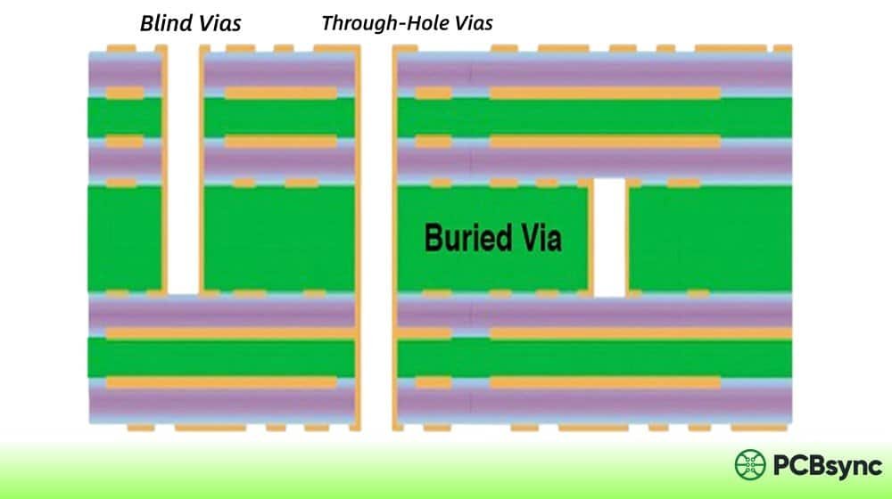
Via Design Considerations
RO3003’s low Z-axis CTE (24 ppm/°C) provides good PTH reliability, but millimeter-wave designs require careful via placement:
Keep vias close to ground planes: Minimize via inductance
Use multiple vias in parallel: Reduce impedance for high-current paths
Consider via fencing: Prevent surface wave propagation in thick substrates
For frequencies above 40 GHz, blind and buried vias or even via-less designs using edge-coupled structures may provide better performance.
Thermal Management
While RO3003’s thermal conductivity (0.50 W/m/K) is better than pure PTFE materials, it’s still lower than FR-4 (~0.25-0.3 W/m/K typical, though this varies). For power amplifier designs:
Use thermal vias under high-power components
Consider copper coin inserts for extreme thermal requirements
Model junction temperatures before finalizing design
Handling and Storage
RO3003 laminates require proper handling to maintain optimal performance:
Storage conditions: Room temperature (13-30°C), moderate humidity
Shelf life: Indefinite at room temperature for dielectric; copper may oxidize in high humidity
Handling: Use clean gloves to prevent contamination
Pre-cleaning: Standard PWB cleaning removes minor oxidation
The ceramic-filled PTFE composition is chemically inert, but copper surfaces can oxidize over extended storage. Store in sealed, moisture-barrier bags for long-term storage, especially in humid climates.
Common Design Mistakes to Avoid
Based on years of debugging RF boards, here are pitfalls to watch for:
Using default FR-4 design rules: RO3003 requires different trace widths for the same impedance
Ignoring frequency-dependent Dk: Use correct Dk values for your operating frequency
Underestimating via inductance: Multiple parallel vias reduce inductance significantly
Mixing incompatible materials: Verify CTE compatibility in hybrid stackups
Specifying wrong copper roughness: Smooth copper reduces conductor loss at mmWave
Skipping simulation: Always verify critical structures with EM simulation
RO3003G2: The Next Generation
Rogers recently introduced RO3003G2 as an enhanced version specifically targeting automotive radar and other demanding mmWave applications. Key improvements include:
Parameter
RO3003
RO3003G2
Insertion Loss
Baseline
~15% lower
Dk at 77 GHz
3.00 (nominal)
3.07 (optimized)
Resin/Filler Content
Standard
Optimized blend
Target Application
General RF/mmWave
Automotive radar primary
If you’re designing specifically for 77 GHz automotive applications, RO3003G2 may offer performance advantages worth evaluating. The material maintains backward compatibility with RO3003 processing techniques.
RO3003 PCB Manufacturing Process
Working with PTFE-based materials requires specialized handling compared to standard FR-4 processing. Here’s what you need to know about fabrication.
Drilling Considerations
RO3003 machines well but requires attention to:
Spindle speed: 180,000-250,000 RPM recommended
Feed rate: 20-60 µm per revolution
Drill bits: Carbide with reduced point angles
The ceramic filler helps with dimensional stability but can accelerate drill wear. Factor in more frequent tool changes for high-volume production.
Etching and Surface Preparation
Standard PTFE etching processes apply to RO3003:
Plasma treatment or sodium-naphthalene etch for surface preparation
Standard alkaline or cupric chloride etching
Post-etch cleaning to remove residues
The ceramic filler improves etch definition compared to unfilled PTFE materials, typically achieving etch shrinkage less than 0.5 mils/inch.
Lamination Parameters
For multilayer RO3003 boards, follow Rogers’ published lamination cycles:
Temperature: Per RO3000 series guidelines
Pressure: Typically lower than FR-4 processes
Cycle time: Extended compared to thermoset materials
Work with PCB manufacturers experienced in PTFE processing. The material isn’t forgiving of process variations, and inexperienced shops can produce unreliable boards.
Surface Finish Options
RO3003 PCB is compatible with most standard surface finishes:
Can cause surface roughness issues at high frequencies
Bare Copper
Special applications
Requires protective coating for storage
For millimeter-wave applications, ENIG with thin nickel layers (typically 2-5 µm) provides the best balance of solderability and RF performance. Thicker nickel can increase conductor losses due to the skin effect.
Quality Standards and Certifications
RO3003 is manufactured under ISO 9001 certification. PCBs fabricated from RO3003 can meet various industry standards:
IPC-6012: Qualification and Performance Specification for Rigid Printed Boards
IPC-6018: Qualification and Performance Specification for High Frequency PCBs
MIL-PRF-31032: Military Performance Specification for PCBs
IATF 16949: Automotive Quality Management System requirements
Ensure your PCB manufacturer holds relevant certifications for your target market, especially for automotive (IATF 16949) or aerospace (AS9100) applications.
Useful Resources for RO3003 PCB Design
Having the right reference materials saves significant design time. Here are the essential resources every RF engineer should bookmark.
Major RF simulation tools include RO3003 in their material libraries:
Ansys HFSS
Keysight ADS
CST Studio Suite
Altium Designer (with RF extensions)
Always verify that your simulation tool uses the correct frequency-dependent Dk values for accurate results above 40 GHz.
Frequently Asked Questions About RO3003 PCB
What is the dielectric constant of RO3003?
RO3003 has a dielectric constant (Dk) of 3.00 ± 0.04 when measured at 10 GHz and 23°C using the clamped stripline method per IPC-TM-650 2.5.5.5. The design Dk remains 3.00 across the 8-40 GHz frequency range, making impedance calculations consistent throughout this band. This stability eliminates the common problem of Dk drift seen in other PTFE materials.
Can RO3003 be used for 77 GHz applications?
Yes, RO3003 is specifically designed for millimeter-wave applications including 77 GHz automotive radar. The material’s ultra-low dissipation factor (0.0010 at 10 GHz), stable dielectric constant, and absence of glass weave make it one of the most popular choices for 77 GHz circuit design. Rogers even developed the RO3003G2 variant with optimized properties specifically targeting automotive radar applications.
What is the difference between RO3003 and RO4003?
The main differences are material composition and loss characteristics. RO3003 is a ceramic-filled PTFE composite with Dk of 3.00 and Df of 0.0010, while RO4003C is a thermoset hydrocarbon/ceramic material with Dk of 3.38 and Df of 0.0027. RO3003 offers lower loss and better high-frequency performance (suitable to 77+ GHz), while RO4003C is easier to process using standard FR-4 fabrication techniques and is more cost-effective for applications below 40 GHz.
What thickness options are available for RO3003?
Standard RO3003 thicknesses include 0.005″ (0.13 mm), 0.010″ (0.25 mm), 0.020″ (0.50 mm), 0.030″ (0.75 mm), and 0.060″ (1.52 mm). Copper cladding options range from ¼ oz to 2 oz in both electrodeposited and reverse-treated foils. Standard panel sizes are 12″×18″ and 24″×18″. Custom configurations may be available through Rogers or authorized distributors.
Is RO3003 suitable for multilayer PCB designs?
Absolutely. RO3003’s consistent mechanical properties and matched CTE with copper make it excellent for multilayer constructions. The material can be combined with itself using RO3003 bonding film, or used in hybrid stackups with other Rogers materials like RO4450F bondply. The uniform Dk across different RO3000 series variants also allows designers to mix different dielectric constant materials in the same board without warpage issues, enabling optimized designs for complex RF front-ends.
Final Thoughts
The RO3003 PCB has earned its reputation as a workhorse material for high-frequency design. Its combination of ultra-low loss, exceptional Dk stability, and practical manufacturability makes it the go-to choice for applications ranging from automotive radar to 5G infrastructure.
Is it the right material for every project? Not necessarily. For lower frequencies or extremely cost-sensitive applications, RO4003C or even enhanced FR-4 variants might make more sense. For the absolute lowest loss at 90+ GHz, RT/duroid 5880 might edge ahead.
But for the sweet spot of 10-77 GHz applications where you need proven performance, reasonable cost, and reliable supply, RO3003 remains hard to beat. The material has been refined over decades of field experience, and its widespread adoption means you’ll find plenty of design examples, simulation models, and fabrication expertise to draw from.
Whatever your next RF project demands, understanding RO3003’s capabilities—and limitations—puts you in the best position to make smart material choices.
Inquire: Call 0086-755-23203480, or reach out via the form below/your sales contact to discuss our design, manufacturing, and assembly capabilities.
Quote: Email your PCB files to Sales@pcbsync.com (Preferred for large files) or submit online. We will contact you promptly. Please ensure your email is correct.
Notes: For PCB fabrication, we require PCB design file in Gerber RS-274X format (most preferred), *.PCB/DDB (Protel, inform your program version) format or *.BRD (Eagle) format. For PCB assembly, we require PCB design file in above mentioned format, drilling file and BOM. Click to download BOM template To avoid file missing, please include all files into one folder and compress it into .zip or .rar format.


