Inquire: Call 0086-755-23203480, or reach out via the form below/your sales contact to discuss our design, manufacturing, and assembly capabilities.
Quote: Email your PCB files to Sales@pcbsync.com (Preferred for large files) or submit online. We will contact you promptly. Please ensure your email is correct.
Notes: For PCB fabrication, we require PCB design file in Gerber RS-274X format (most preferred), *.PCB/DDB (Protel, inform your program version) format or *.BRD (Eagle) format. For PCB assembly, we require PCB design file in above mentioned format, drilling file and BOM. Click to download BOM template To avoid file missing, please include all files into one folder and compress it into .zip or .rar format.
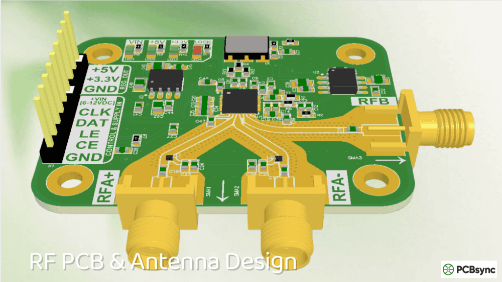
If you’ve spent any time designing base station antennas or working on cellular infrastructure projects, you know PIM can make or break your design. I’ve seen antenna projects fail testing because the engineering team picked the wrong substrate—and that’s an expensive mistake nobody wants to repeat.
Rogers Corporation’sIM Series Laminatesrepresent what I consider the gold standard for ultra-low PIM antenna applications. These aren’t just another PTFE material option; they’re specifically engineered to solve the passive intermodulation challenges that keep RF engineers up at night.
In this guide, I’ll walk you through everything you need to know about IM Series Laminates—from the technical specs that matter to real-world application considerations. Whether you’re specifying materials for a 5G deployment or troubleshooting PIM issues on an existing design, this information will help you make better decisions.
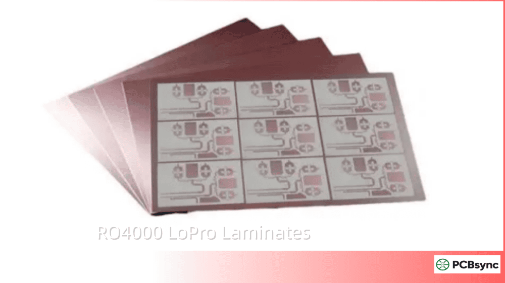
IM Series Laminates are high-frequency antenna-grade circuit materials manufactured by Rogers Corporation. The “IM” designation stands for the proprietary IM cladding system—an ultra-smooth electrodeposited copper foil technology that dramatically reduces passive intermodulation.
Here’s the key thing to understand: IM Series isn’t a standalone material family. Instead, it’s an enhanced cladding option available for three proven Rogers antenna substrates:
AD300D-IM (Dk = 2.97)
AD255C-IM (Dk = 2.55)
DiClad 880-IM (Dk = 2.17)
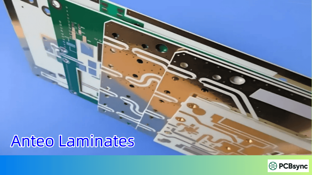
All three variants share the same fundamental composition—PTFE resin systems reinforced with woven fiberglass for dimensional stability. What sets them apart from standard antenna laminates is that IM cladding solution.
The IM Cladding Technology
The breakthrough here is copper surface roughness. Standard reverse-treated electrodeposited copper (S1/S1) has a surface roughness of approximately Rq = 1.0µm. The IM cladding cuts that in half to Rq = 0.5µm, measured using non-contact interferometry.
Why does roughness matter so much? Copper surface roughness directly correlates with PIM generation. The smoother the copper-dielectric interface, the lower your intermodulation products. Rogers’ testing shows approximately 6 dB average improvement in PIM performance compared to previous-generation AD300C material with standard copper.
The real engineering achievement is maintaining excellent copper adhesion despite the smoother surface. That’s historically been the trade-off—smoother copper typically meant weaker bonding to the substrate. Rogers solved this with their IM foil chemistry.
Before diving deeper into specifications, let’s talk about why passive intermodulation has become such a critical parameter.
PIM occurs when two or more high-power signals mix in a passive component, generating unwanted spurious signals at frequencies that can fall directly into your receive band. In a base station antenna handling multiple carriers at 43 dBm each, those intermodulation products—even at -150 dBc or lower—can raise your noise floor enough to degrade receiver sensitivity.
The practical consequences include:
Reduced system capacity – Higher noise floors mean fewer simultaneous users
Dropped calls – Marginal signals get lost in the noise
Lower data rates – Modulation schemes fall back to more robust (slower) modes
Failed site acceptance testing – Carriers won’t accept infrastructure that doesn’t meet PIM specs
Modern 4G LTE and 5G FDD systems typically require PIM levels of -153 dBc or better. Many operators now specify -160 dBc. The IM Series materials deliver typical values of -166 dBc at 0.030″ thickness—providing meaningful margin against these requirements.
IM Series Laminates Technical Specifications
Let me break down the specifications that matter for design work. I’ve pulled this data from the Rogers datasheet and organized it by property category.
With three IM Series options available, selecting the right one depends on your specific design requirements. Here’s how I approach the decision:
AD300D-IM: The Workhorse
Dk = 2.94 (process) | Df = 0.0021
AD300D-IM is the most commonly specified IM Series laminate for cellular infrastructure antennas. The Dk of approximately 3.0 allows reasonable miniaturization while the ceramic filling provides excellent dimensional stability and the lowest Z-axis CTE (98 ppm/°C) of the three options.
Best for: Base station microstrip antennas, patch antenna elements, applications requiring tight Dk tolerance (±0.05)
AD255C-IM: Mid-Range Flexibility
Dk = 2.55 (process) | Df = 0.0014
AD255C-IM sits between the other two options in terms of dielectric constant. It offers lower loss than AD300D-IM while providing better miniaturization than DiClad 880-IM.
Best for: Applications balancing size constraints with loss requirements, moderate miniaturization needs
DiClad 880-IM: Ultra-Low Loss
Dk = 2.17 (process) | Df = 0.0009
When loss performance is your primary concern, DiClad 880-IM delivers the lowest dissipation factor of any IM Series material. The lower Dk means larger antenna elements, but the electrical performance is exceptional.
Best for: Feed networks, diplexers, applications where insertion loss is critical
The IM Series materials were specifically developed for PIM-sensitive antenna applications. Here’s where they excel:
Cellular Infrastructure Base Station Antennas
This is the primary application driving IM Series development. Modern base station antennas for LTE and 5G networks must meet stringent PIM requirements—often -155 dBc or better. The IM cladding’s consistent -166 dBc performance provides comfortable margin for production variation and environmental factors.
The woven glass reinforcement proves critical here. Large antenna panels require excellent dimensional stability across temperature cycling and humidity exposure. IM Series materials maintain their mechanical form during handling and assembly, improving manufacturing yields.
WiMax and Carrier-Grade WiFi Networks
Licensed and unlicensed wireless networks in the 2.4-5.8 GHz range benefit from IM Series performance characteristics. The low loss tangent preserves signal integrity in feed distribution networks, while consistent PIM performance prevents self-interference in collocated deployments.
5G Massive MIMO Arrays
The evolution toward active antenna arrays and massive MIMO configurations places additional demands on PCB materials. Multiple antenna elements on a single panel mean multiple potential PIM sources—making consistent, low-PIM substrate materials essential.
IM Series laminates support these designs with:
Predictable electrical performance across large panel areas
Excellent batch-to-batch consistency for volume production
Compatibility with standard PTFE fabrication processes
Satellite and Aerospace Communications
While not the primary target market, the IM Series materials meet NASA outgassing requirements (TML/CVCM = 0.01%/0.01%) for space-qualified applications. The low moisture absorption (0.02-0.04%) ensures stable performance in varying humidity environments.
PCB Fabrication Considerations for IM Series Laminates
If you’re working with a PCB fabricator on an IM Series design, here are the practical considerations I’ve found most important.
Processing Compatibility
IM Series laminates are compatible with standard PTFE fabrication processes. If your fabricator has experience with Rogers AD Series or DiClad materials, they can handle IM Series without significant process changes.
Key fabrication notes:
Drilling: Standard carbide tooling works well. PTFE materials are generally forgiving compared to hard ceramics
Plating: The IM copper surface bonds well with electroless copper during through-hole plating
Etching: Standard alkaline etchants work. The smooth copper surface may etch slightly faster—verify with test coupons
Soldermask: Most standard soldermasks adhere adequately. Plasma treatment before application improves adhesion
Standard Availability
Rogers offers IM Series materials in standard configurations:
Non-standard thicknesses and configurations may be available—contact Rogers Sales Engineering for custom requirements.
Design Guidelines
When designing with IM Series materials:
Account for Dk tolerance: The ±0.05 Dk tolerance is tighter than most PTFE materials, but still factor it into impedance calculations
Use design Dk values: For microstrip designs, use the “design” Dk values from the datasheet rather than process values
Consider TCDk: AD300D-IM has the best temperature stability (-73 ppm/°C). If your antenna operates across wide temperature ranges, this matters
Minimize via count: While not specific to IM Series, fewer vias means fewer potential PIM sources
IM Series vs. Other Rogers Antenna Laminates
How do IM Series materials compare to other options? Here’s a practical comparison:
IM Series vs. Standard AD Series
The IM Series uses the same base substrates as standard AD300D, AD255C, and DiClad 880—the difference is copper cladding. Standard materials with S1/S1 copper typically achieve -159 dBc PIM performance. The IM cladding improves this to -166 dBc (typical) with significantly tighter distribution.
When to choose IM Series: Projects with PIM specs tighter than -155 dBc, or when production yield on PIM testing is a concern.
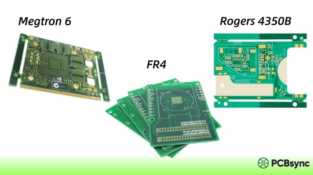
IM Series vs. RO4000 Series
RO4000 materials (RO4003C, RO4350B, RO4500, RO4700 series) use hydrocarbon ceramic technology rather than PTFE. They process like FR-4 and cost less than PTFE options.
Factor
IM Series
RO4000 Series
PIM Performance
-166 dBc (typical)
-155 to -160 dBc
Loss Tangent
0.0009 – 0.0021
0.0021 – 0.0037
Processing
PTFE methods
FR-4 compatible
Relative Cost
Higher
Lower
Best For
Ultra-low PIM
Multilayer integration
When to choose RO4000: Projects where PIM specs allow -155 dBc or where multilayer construction with FR-4 processing is required.
IM Series vs. RT/duroid
RT/duroid materials are Rogers’ premium PTFE offerings with exceptional electrical properties. However, they weren’t specifically optimized for low PIM the way IM Series materials were.
When to choose RT/duroid: Space applications, extremely high frequency designs (>40 GHz), or where specific RT/duroid heritage is required.
Useful Resources and Documentation
For your reference, here are the key technical resources for IM Series Laminates:
Rogers Technology Support Hub: White papers, calculators, application notes
Regional Sales Contacts: For custom configurations and pricing
Applications Engineering: Technical support for design challenges
Frequently Asked Questions About IM Series Laminates
What is the typical PIM performance of IM Series Laminates?
IM Series Laminates achieve typical PIM values of -166 dBc at 0.030″ thickness and -165 dBc at 0.060″ thickness. These measurements use Rogers’ internal test method with two 43 dBm swept tones at 1900 MHz. The IM cladding has also been evaluated at frequencies as low as 710 MHz with even better results. What’s equally important is the tighter distribution—the standard deviation of PIM values with IM cladding is significantly improved versus standard S1 copper.
How do IM Series Laminates compare to standard AD Series materials?
IM Series Laminates use the same base substrates (AD300D, AD255C, DiClad 880) but feature the proprietary IM cladding system with ultra-smooth copper (Rq = 0.5µm versus 1.0µm for standard S1 copper). This results in approximately 6-7 dB better PIM performance—from around -159 dBc with standard cladding to -166 dBc with IM cladding. Electrical properties of the dielectric material remain identical.
What thicknesses are available for IM Series Laminates?
Standard thicknesses are 0.030″ (0.762 mm) and 0.060″ (1.524 mm). These cover most base station antenna applications. Non-standard thicknesses may be available through Rogers custom manufacturing—contact Sales Engineering to discuss specific requirements and minimum order quantities.
Can IM Series Laminates be used in multilayer PCB constructions?
While IM Series materials can technically be incorporated into multilayer designs, they’re primarily optimized for single-layer antenna element and feed network applications. For complex multilayer constructions requiring FR-4-style processing, the RO4000 series (RO4003C, RO4350B) often provides better manufacturability. If your multilayer design has critical PIM requirements, discuss bonding options with your fabricator and Rogers applications engineering.
What is the operating temperature range for IM Series Laminates?
IM Series materials have a decomposition temperature (Td) exceeding 550°C and time to delamination greater than 60 minutes at 288°C. For operational purposes, they’re suitable across the typical military and commercial temperature ranges (-55°C to +125°C). The temperature coefficient of dielectric constant (TCDk) varies by grade: AD300D-IM at -73 ppm/°C provides the best Dk stability over temperature, while DiClad 880-IM at -160 ppm/°C shows more variation.
Conclusion
IM Series Laminates represent Rogers Corporation’s most advanced solution for PIM-critical antenna applications. The combination of proven PTFE substrates with ultra-smooth IM cladding technology delivers consistent -166 dBc performance that meets the demands of modern 4G LTE, 5G, and carrier-grade wireless deployments.
For RF engineers working on base station antennas, the choice between AD300D-IM, AD255C-IM, and DiClad 880-IM comes down to balancing dielectric constant (miniaturization potential), loss tangent (efficiency), and cost for your specific application. All three deliver the low-PIM performance that makes IM Series materials the substrate of choice for demanding antenna designs.
If you’re evaluating materials for an upcoming project, I’d recommend requesting samples through Rogers’ online portal and running your own PIM characterization. The datasheet numbers are solid, but there’s no substitute for validating performance on your actual design.
Inquire: Call 0086-755-23203480, or reach out via the form below/your sales contact to discuss our design, manufacturing, and assembly capabilities.
Quote: Email your PCB files to Sales@pcbsync.com (Preferred for large files) or submit online. We will contact you promptly. Please ensure your email is correct.
Notes: For PCB fabrication, we require PCB design file in Gerber RS-274X format (most preferred), *.PCB/DDB (Protel, inform your program version) format or *.BRD (Eagle) format. For PCB assembly, we require PCB design file in above mentioned format, drilling file and BOM. Click to download BOM template To avoid file missing, please include all files into one folder and compress it into .zip or .rar format.


