Inquire: Call 0086-755-23203480, or reach out via the form below/your sales contact to discuss our design, manufacturing, and assembly capabilities.
Quote: Email your PCB files to Sales@pcbsync.com (Preferred for large files) or submit online. We will contact you promptly. Please ensure your email is correct.
Notes: For PCB fabrication, we require PCB design file in Gerber RS-274X format (most preferred), *.PCB/DDB (Protel, inform your program version) format or *.BRD (Eagle) format. For PCB assembly, we require PCB design file in above mentioned format, drilling file and BOM. Click to download BOM template To avoid file missing, please include all files into one folder and compress it into .zip or .rar format.
If you’ve spent any time designing RF or microwave circuits, you know the headache of finding materials that actually hold up under demanding conditions. I’ve been working with high-frequency laminates for years, and CLTE-XT consistently proves itself when projects require tight phase control and rock-solid dimensional stability.
This guide breaks down everything you need to know about CLTE-XT—from raw specifications to real-world fabrication tips that’ll save you time and scrap boards.
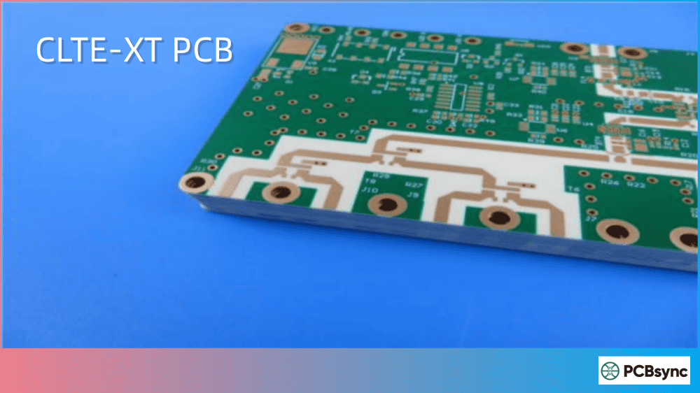
CLTE-XT is a ceramic-filled PTFE composite laminate manufactured by Rogers Corporation. The “XT” stands for “Extended Technology”—Rogers’ way of indicating this is an enhanced version of the original CLTE material with improved loss characteristics.
The material combines three key components:
PTFE (Polytetrafluoroethylene): Provides the low-loss dielectric foundation
Micro-dispersed ceramic filler: Adds dimensional stability and controls thermal expansion
Woven fiberglass reinforcement: Delivers mechanical strength for multilayer processing
What sets CLTE-XT apart from standard PTFE laminates is its exceptional phase stability across temperature extremes. When you’re designing phase-fed antenna arrays or precision filters that need to perform from -40°C to +140°C, this stability becomes mission-critical.
CLTE-XT Material Composition
The ceramic loading in CLTE-XT serves multiple purposes. It lowers the coefficient of thermal expansion (CTE) to match copper more closely, which dramatically improves plated through-hole reliability. It also increases thermal conductivity compared to unfilled PTFE, helping with heat dissipation in power amplifier applications.
CLTE-XT Electrical Properties and Specifications
Let me walk you through the numbers that matter when you’re evaluating CLTE-XT for your next design.
The standout specification here is the dissipation factor of 0.0010 at 10 GHz. This gives CLTE-XT the lowest insertion loss in its class—roughly half the loss of the standard CLTE material (0.0021). For feed networks and antenna manifolds where every fraction of a dB counts, this difference directly translates to improved system performance.
Dielectric Constant by Thickness
One critical detail that catches many designers off guard: CLTE-XT’s dielectric constant varies with laminate thickness. This isn’t a defect—it’s a characteristic of the woven glass reinforcement ratio. Here’s what you need for accurate impedance calculations:
Nominal Thickness
Dk Value (10 GHz)
Dk Tolerance
0.0051″ (0.130 mm)
2.79
±0.03
0.0094″ (0.239 mm)
2.89
±0.03
0.020″ (0.508 mm)
2.92
±0.03
0.030″ (0.762 mm)
2.94
±0.03
That ±0.03 Dk tolerance is the tightest in the CLTE family. When you’re designing phase-matched networks or tightly controlled impedance lines, this consistency across production lots is invaluable.
CLTE-XT Thermal Properties
Thermal performance often makes or breaks high-reliability designs. Here’s where CLTE-XT really earns its keep.
Thermal Specifications Table
Property
CLTE-XT Value
Test Conditions
Test Method
Decomposition Temperature (Td)
539°C
5% weight loss, 2hrs @ 105°C
IPC TM-650 2.3.40
CTE X-axis
12.7 ppm/°C
-55°C to 288°C
IPC TM-650 2.4.41
CTE Y-axis
13.7 ppm/°C
-55°C to 288°C
IPC TM-650 2.4.41
CTE Z-axis
40.8 ppm/°C
-55°C to 288°C
IPC TM-650 2.4.41
Thermal Conductivity
0.56 W/(m·K)
Z-direction
ASTM D5470
Time to Delamination @ 288°C
>60 minutes
As-received
IPC TM-650 2.4.24.1
The Z-axis CTE of 40.8 ppm/°C deserves attention. It’s significantly lower than many PTFE-based alternatives, which means your plated through-holes won’t experience the barrel cracking that plagues boards subjected to repeated thermal cycling.
Phase Stability Across Temperature
What really distinguishes CLTE-XT for phase-sensitive applications is how the dielectric constant behaves across temperature. The Dk versus temperature curve remains remarkably flat from -40°C to +140°C. For phased array radar systems where beam pointing accuracy depends on consistent electrical length, this stability directly impacts target tracking precision.
CLTE-XT Applications in Defense and Commercial Systems
CLTE-XT finds its home in applications where failure isn’t an option and performance margins are thin. The material’s unique combination of phase stability, low loss, and thermal reliability makes it a go-to choice across multiple industries.
Defense and Aerospace Applications
Phased Array Antennas: The tight Dk tolerance and phase stability make CLTE-XT a natural fit for phased array systems. Whether you’re designing for AESA (Active Electronically Scanned Array) radar or satellite communications terminals, consistent electrical performance across thousands of radiating elements is essential. Modern phased arrays can contain over 1,000 transmit/receive modules—any Dk variation between elements directly translates to beam pointing error.
Radar Manifolds: Corporate feed networks for radar systems require precise power splitting with minimal loss. CLTE-XT’s low Df keeps insertion loss under control while dimensional stability maintains the phase relationships your combiner networks depend on. In multibeam antenna feeds, even 0.5 dB of excess loss compounds across dozens of power dividers.
CNI Systems: Communications, Navigation, and Identification avionics operate across wide frequency bands and temperature ranges. CLTE-XT handles both requirements without performance degradation. Military aircraft experience extreme temperature cycling—from cold-soaked at altitude to hot tarmac conditions—making thermal stability non-negotiable.
SIGINT and Electronic Warfare: Signal intelligence receivers need low-loss front ends to maintain sensitivity. The noise figure of an RF chain depends heavily on the losses preceding the LNA. CLTE-XT’s electrical properties support the wideband performance these systems demand while minimizing contributions to system noise.
Space and Satellite Electronics: CLTE-XT’s low outgassing characteristics (TML 0.02%, CVCM 0.00%) qualify it for space applications. The material won’t contaminate sensitive optical surfaces or solar cells, and it withstands the thermal cycling of orbital day/night transitions.
Commercial and Automotive Applications
ADAS Radar (77 GHz): Advanced Driver Assistance Systems push well into the millimeter-wave spectrum. CLTE-XT’s stable properties at higher frequencies support automotive radar modules for collision avoidance, adaptive cruise control, blind spot detection, and autonomous driving features. As vehicle manufacturers push toward Level 4 autonomy, radar sensor reliability becomes safety-critical.
5G Infrastructure: Massive MIMO antenna arrays for 5G base stations benefit from CLTE-XT’s combination of low loss and consistent Dk for beamforming accuracy. With 64 or 128 antenna elements per panel, any variation in electrical properties translates directly to degraded beam patterns and reduced network capacity.
Satellite Communications: Both ground terminals and space-qualified assemblies use CLTE-XT. The material’s low outgassing characteristics (TML 0.02%, CVCM 0.00% per ASTM E595) meet NASA requirements for space hardware. LEO satellite constellations like Starlink and OneWeb drive demand for cost-effective, high-performance antenna substrates.
Test and Measurement Equipment: Precision RF test equipment—network analyzers, spectrum analyzers, signal generators—requires substrates that don’t introduce measurement uncertainty. CLTE-XT’s consistent properties make it suitable for calibration standards and reference circuits.
Medical Imaging: High-frequency imaging systems, including certain MRI receiver coils and microwave imaging research platforms, benefit from CLTE-XT’s stable electrical properties and biocompatibility of PTFE-based materials.
CLTE-XT vs Other Rogers High-Frequency Materials
Choosing the right laminate means understanding the trade-offs. Here’s how CLTE-XT stacks up against alternatives you’re likely considering.
Ultra-low Dk is required (RT/duroid 5880 offers 2.20)
Standard commercial temperature ranges are sufficient
CLTE-XT PCB Fabrication Guidelines
Working with CLTE-XT requires some adjustments to standard FR-4 processes. Here’s what your fabrication shop needs to know.
Drilling Recommendations
CLTE-XT machines well with carbide tooling, but there are a few key points:
Use highly polished carbide drill bits—repointed tools aren’t recommended
Stack heights should be based on total thickness rather than panel count
Entry and backup materials help prevent delamination at hole walls
For vias under 0.3mm, consider laser drilling for cleaner results
Imaging and Etching
The good news: conventional dry film and wet processing work fine with CLTE-XT. Standard ammoniacal or cupric etchants remove copper without attacking the laminate. However, avoid mechanical scrubbing of the PTFE surface—it can cause dimensional changes that throw off your registration.
Multilayer Lamination with CLTE-P Prepreg
For multilayer CLTE-XT builds, Rogers provides CLTE-P bonding ply. This prepreg matches the Dk of the core laminate, maintaining consistent electrical properties through the stackup.
Critical process parameters:
Parameter
Recommended Value
Lamination Temperature
288–300°C (550–572°F)
Pressure
400 PSI (hydraulic press)
Heat-up Rate
Controlled ramp required
Cool-down
Under pressure, controlled rate
Important: Standard FR-4 black oxide processes won’t work at these temperatures. Use brown or red oxide treatments for copper adhesion, or skip oxide entirely and rely on microetch.
Surface Finishes
CLTE-XT is compatible with all common surface finishes:
Before solder leveling, bake boards for 1-2 hours at 110-120°C to drive out any absorbed moisture. Vacuum baking provides better results than conventional ovens.
Available CLTE-XT Thicknesses and Configurations
Standard Thickness Options
Thickness (inches)
Thickness (mm)
Tolerance
0.0051″
0.130 mm
±0.0005″
0.0094″
0.239 mm
±0.0007″
0.020″
0.508 mm
±0.0010″
0.030″
0.762 mm
±0.0010″
Custom thicknesses are available through Rogers—contact their customer service for non-standard requirements.
Standard Panel Sizes
18″ × 12″ (457 × 305 mm)
18″ × 24″ (457 × 610 mm)
Copper Cladding Options
CLTE-XT ships with electrodeposited or reverse-treated copper in standard weights:
½ oz (18 µm)
1 oz (35 µm)
Rolled copper and heavier weights are available on request. For applications requiring heavy metal backing (heat spreaders or mounting plates), CLTE-XT can be bonded to aluminum, brass, or copper plates.
CLTE-XT Design Considerations
A few practical tips from the design trenches that can save you time and avoid costly respins:
Account for Dk variation: Remember that thinner laminates have lower Dk. If your design mixes thicknesses in a multilayer stackup, model each layer with its actual Dk value. Using a single “typical” Dk across all layers will throw off your impedance calculations.
Use design Dk, not process Dk: Rogers specifies both “process” and “design” dielectric constants. The design value (2.93 for CLTE-XT) accounts for the resin-rich environment around etched traces. Use this value for microstrip and stripline calculations—it’s what you’ll actually measure on finished boards.
Mind your registration: CLTE-XT offers excellent dimensional stability (better than -0.67 mm/m after 4 hours at 105°C), but verify registration requirements with your fab house for complex multilayer builds. The woven glass reinforcement helps, but PTFE-based materials still move more than FR-4.
Thermal management: The 0.56 W/(m·K) thermal conductivity is higher than standard PTFE but lower than ceramic-loaded hydrocarbon laminates like RO4350B. For high-power applications, consider thermal vias, metal backing, or dedicated heat spreader layers. Copper coins embedded under high-dissipation components can dramatically improve thermal performance.
Lead-free assembly: CLTE-XT handles lead-free reflow temperatures (260°C+) without issues. The >60 minute delamination time at 288°C provides adequate margin for multiple reflow cycles. Still, minimize time at peak temperature and ensure adequate preheat to avoid thermal shock.
Copper adhesion: After thermal stress testing (10 seconds at 288°C), CLTE-XT maintains 1.7 N/mm peel strength with 35 µm copper. This exceeds IPC requirements and ensures reliable wire bonding and SMT attachment.
Impedance modeling: For transmission line calculations, start with Rogers’ MWI calculator, then verify with your preferred 2D/3D field solver. The woven glass weave pattern can introduce slight impedance variations along trace length—keep critical traces aligned with the weave direction when possible.
CLTE and CLTE-XT Datasheet (PDF): Available from Rogers’ website under the CLTE Series product documentation
Fabrication Guidelines for CLTE Series: Technical document covering drilling, lamination, and finishing processes
Rogers Laminate Properties Tool: Online comparison tool for filtering and comparing Rogers materials by property
Design Tools
Rogers MWI Calculator: Microwave impedance calculator for transmission line design
Rogers Impedance Calculator: Web-based tool for microstrip and stripline calculations
Sample Request: Rogers offers material samples through their online request system
Industry Standards References
IPC-4103B: Specification for Microwave Base Materials (CLTE-XT is listed under slash sheet /006)
IPC TM-650: Test methods referenced throughout the datasheet
ASTM E595: NASA outgassing test standard for space applications
Frequently Asked Questions About CLTE-XT
What is the difference between CLTE and CLTE-XT?
CLTE-XT is the “Extended Technology” version with approximately half the loss tangent (0.0010 vs 0.0021 at 10 GHz) and improved Z-axis CTE (40.8 vs 57.9 ppm/°C). CLTE-XT also maintains its properties over a wider temperature range. The trade-off is cost—CLTE-XT commands a premium over standard CLTE.
Can CLTE-XT be used in multilayer PCB designs?
Yes. Rogers provides CLTE-P prepreg specifically for bonding CLTE-XT layers. The prepreg is Dk-matched to the core laminate and requires lamination at 288-300°C. Successful multilayer fabrication requires following Rogers’ specific process guidelines—standard FR-4 lamination parameters won’t work.
Is CLTE-XT suitable for space applications?
CLTE-XT meets NASA outgassing requirements with TML (Total Mass Loss) of 0.02% and CVCM (Collected Volatile Condensable Materials) of 0.00% per ASTM E595. This makes it appropriate for satellite and space electronics where outgassing can contaminate optics or sensitive surfaces.
What frequencies can CLTE-XT support?
CLTE-XT performs well from low GHz through millimeter-wave frequencies. The dissipation factor remains stable up to at least 30 GHz based on published data. For 77 GHz automotive radar applications, verify specific Dk and Df values with Rogers’ applications engineering team.
How does CLTE-XT compare to RO4350B for cost-sensitive projects?
RO4350B costs significantly less than CLTE-XT and processes more like FR-4, making it attractive for volume production. However, CLTE-XT offers lower loss (Df 0.0010 vs 0.0037), tighter Dk tolerance (±0.03 vs ±0.05), and superior phase stability with temperature. For applications where these parameters drive system performance, the CLTE-XT premium is justified.
Conclusion
CLTE-XT earns its place in demanding high-frequency designs through a combination of low loss, exceptional dimensional stability, and rock-solid performance across temperature extremes. It’s not the cheapest option, and it requires more careful fabrication than hydrocarbon ceramics like RO4350B, but for phase-sensitive systems and high-reliability applications, the material delivers where it counts.
When you’re specifying CLTE-XT, work closely with both Rogers’ applications support and your PCB fabricator to nail down the process parameters. The performance is there—you just need the right fabrication partner to bring it out.
Inquire: Call 0086-755-23203480, or reach out via the form below/your sales contact to discuss our design, manufacturing, and assembly capabilities.
Quote: Email your PCB files to Sales@pcbsync.com (Preferred for large files) or submit online. We will contact you promptly. Please ensure your email is correct.
Notes: For PCB fabrication, we require PCB design file in Gerber RS-274X format (most preferred), *.PCB/DDB (Protel, inform your program version) format or *.BRD (Eagle) format. For PCB assembly, we require PCB design file in above mentioned format, drilling file and BOM. Click to download BOM template To avoid file missing, please include all files into one folder and compress it into .zip or .rar format.


