Inquire: Call 0086-755-23203480, or reach out via the form below/your sales contact to discuss our design, manufacturing, and assembly capabilities.
Quote: Email your PCB files to Sales@pcbsync.com (Preferred for large files) or submit online. We will contact you promptly. Please ensure your email is correct.
Notes: For PCB fabrication, we require PCB design file in Gerber RS-274X format (most preferred), *.PCB/DDB (Protel, inform your program version) format or *.BRD (Eagle) format. For PCB assembly, we require PCB design file in above mentioned format, drilling file and BOM. Click to download BOM template To avoid file missing, please include all files into one folder and compress it into .zip or .rar format.
If you’re designing circuits for 5G infrastructure or millimeter-wave applications, choosing the right laminate can make or break your project. CLTE-MW has become one of the go-to materials for RF engineers working in the 24GHz to 77GHz range—and for good reason. This ceramic-filled PTFE composite delivers the low-loss performance that mmWave designs demand, without the astronomical price tag of some competing materials.
I’ve worked with dozens of high-frequency laminates over the years, and CLTE-MW stands out for its combination of electrical performance, fabrication friendliness, and cost-effectiveness. In this guide, I’ll walk you through everything you need to know about this material—from specifications and applications to design tips and comparisons with alternatives.
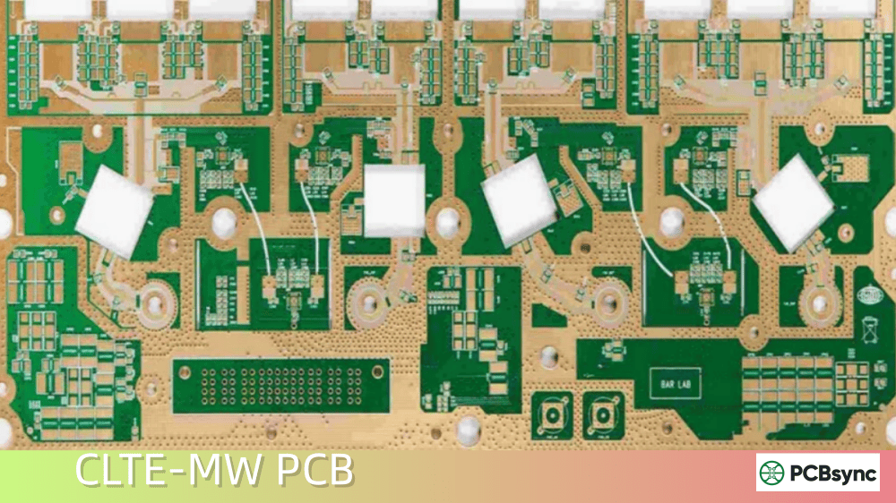
Rogers CLTE-MW is a ceramic-filled, woven glass reinforced PTFE (polytetrafluoroethylene) composite laminate developed specifically for 5G and millimeter-wave applications. It belongs to Rogers Corporation’s CLTE Series, which focuses on materials with low coefficients of thermal expansion (CTE) for improved reliability.
What makes CLTE-MW unique is its spread glass reinforcement combined with high ceramic filler loading. This construction minimizes the “glass weave effect”—that annoying Dk variation you get when your signal crosses different parts of the weave pattern. At mmWave frequencies, this variation can wreak havoc on your impedance control, so having a material that addresses this problem from the ground up is valuable.
Key Characteristics of CLTE-MW
Material composition: Ceramic-filled PTFE with woven glass reinforcement
Target frequency range: 24 GHz to 77+ GHz (5G mmWave, automotive radar)
The seven thickness options are particularly helpful when you’re trying to hit specific impedance targets. In mmWave designs, getting the right signal-to-ground spacing is critical for maintaining transmission line performance.
CLTE-MW Technical Specifications
Let me break down the key specifications you’ll need for your design work. I’ve organized these into categories that match what you’d typically look for when evaluating a laminate.
The 0.0015 loss tangent at 10 GHz is competitive with many premium PTFE materials. You won’t get the ultra-low 0.0009 of RT/duroid 5880, but for most 5G and automotive radar applications, this level of loss is more than acceptable—especially considering the cost difference.
That 30 ppm/°C Z-axis CTE deserves special attention. It’s low enough to provide good plated through-hole reliability—critical if you’re building multilayer mmWave assemblies with multiple lamination cycles.
Mechanical Properties
Parameter
Value
Moisture Absorption
0.03%
Flammability Rating
UL 94 V-0
Copper Cladding Options
Rolled, ED, Reverse-treated ED
The ultra-low 0.03% moisture absorption means your Dk stays stable across different humidity conditions. This matters more than you might think in production environments or field-deployed equipment.
CLTE-MW finds its sweet spot in applications where you need millimeter-wave performance without breaking the budget. Here are the primary use cases I’ve seen in practice:
5G Millimeter-Wave Infrastructure
The 5G FR2 bands (24.25-52.6 GHz) require PCB materials that can handle high frequencies with minimal signal degradation. CLTE-MW’s stable Dk and low loss make it well-suited for:
mmWave base station antennas
Phased array antenna elements
Backhaul radio systems
Small cell equipment
The thin laminate options (3-10 mils) are particularly valuable here. At mmWave frequencies, your transmission line widths shrink dramatically, and getting the right dielectric thickness is crucial for maintaining 50Ω impedance without going to impractically narrow traces. Having seven thickness options lets you optimize your stackup without compromising on impedance control.
The spread glass construction also addresses a practical concern in phased array designs: phase consistency across the aperture. When you have dozens or hundreds of antenna elements, even small Dk variations between them can throw off your beam steering accuracy. CLTE-MW’s high filler loading and spread glass help minimize this variation.
Automotive Radar Systems
Modern vehicles use 77 GHz radar for adaptive cruise control, collision avoidance, and autonomous driving features. CLTE-MW supports these applications with:
Consistent electrical performance across temperature extremes (-40°C to +125°C)
Good dimensional stability for antenna patterns
Reliable plated through-holes for multilayer designs
Low moisture absorption for underhood environments
Automotive radar is one of the fastest-growing applications for mmWave PCB materials. The combination of high-volume production requirements and demanding performance specs pushes manufacturers toward materials like CLTE-MW that balance cost and capability. You’re not going to use RT/duroid 5880 in a mass-market vehicle radar module—the economics don’t work. But you also can’t use standard automotive-grade laminates because they fall apart at 77 GHz.
The temperature stability is particularly important here. Your radar needs to work whether it’s -30°C on a Minnesota winter morning or +85°C inside an engine compartment in Arizona summer. CLTE-MW’s low thermal coefficient of dielectric constant (TCDk) helps maintain consistent radar performance across this range.
Aerospace and Defense
Military communications, electronic warfare systems, and satellite communications often operate at mmWave frequencies. CLTE-MW offers:
Low outgassing (important for space applications)
Excellent reliability in harsh environments
Compatibility with stringent mil-spec requirements
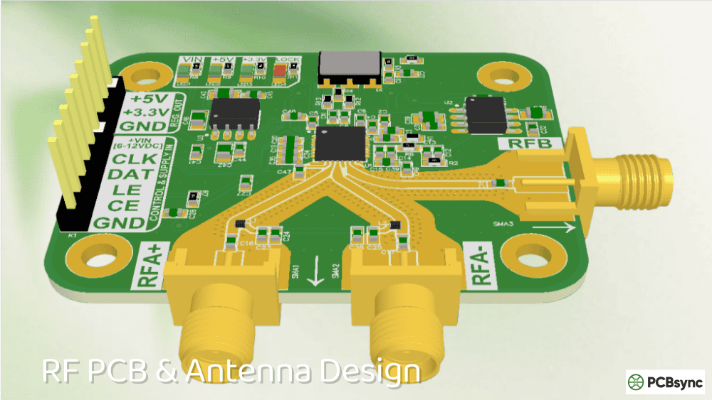
General RF Components
Beyond these specific markets, CLTE-MW works well for various RF building blocks:
Amplifiers
Baluns
Couplers
Filters
Power dividers
CLTE-MW vs Other Rogers Materials
Choosing between Rogers materials often comes down to balancing performance, cost, and fabrication complexity. Here’s how CLTE-MW stacks up against common alternatives:
You need thin substrates (3-10 mil) for proper impedance matching
Cost is a consideration but you can’t compromise on mmWave performance
You want spread glass construction to minimize glass weave effects
You’re building phased arrays where Dk uniformity matters
Your application requires UL 94 V-0 flame rating
Consider other materials when:
You need the absolute lowest loss (go with RT/duroid 5880)
Your design primarily operates below 10 GHz (RO4350B offers good value)
You need higher thermal conductivity for power applications
You require FR-4-compatible processing (RO4000 series is easier)
You need a lower Dk for specific impedance requirements
Cost Considerations
While I can’t quote specific prices (they vary by supplier, quantity, and market conditions), CLTE-MW generally falls in the mid-range of high-frequency laminates. It’s more expensive than RO4000 series materials but less expensive than premium offerings like RT/duroid 5880 or RO3003. For production volumes, the cost difference can be significant—sometimes 30-50% or more between material families.
The real cost analysis should include fabrication yield, not just material price. CLTE-MW’s woven glass reinforcement provides better dimensional stability than unreinforced PTFE materials, which can improve yields in multilayer constructions. The UL 94 V-0 rating also simplifies regulatory compliance for commercial products.
PCB Design Tips for CLTE-MW
Working with PTFE-based materials like CLTE-MW requires some adjustments to your typical design and fabrication approach. Here are practical tips based on real-world experience:
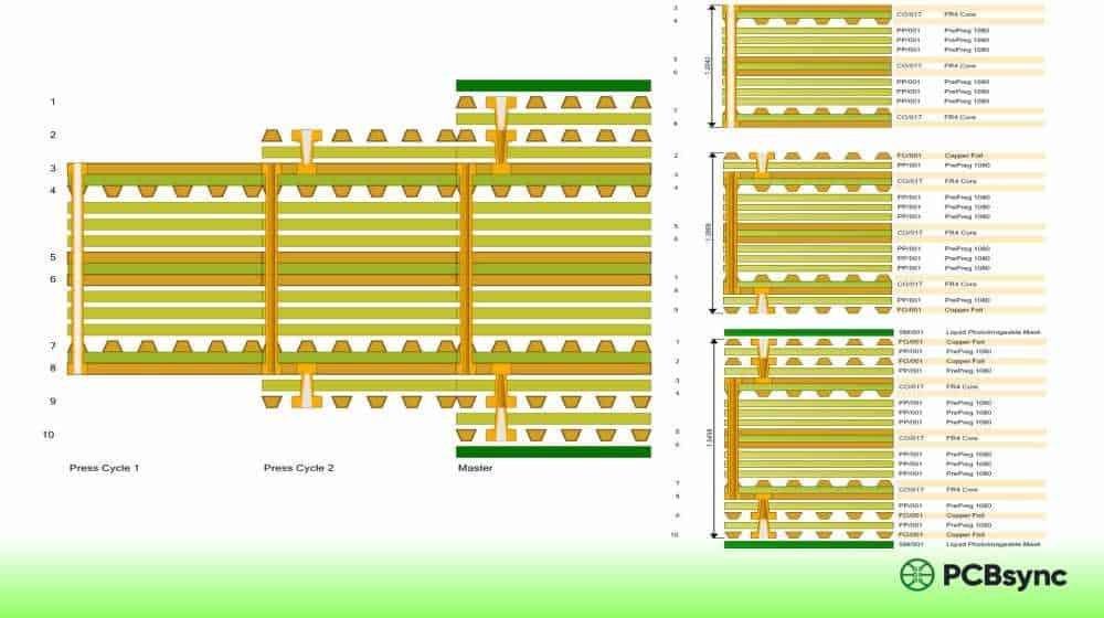
Stack-up Considerations
For multilayer mmWave designs, consider using CLTE-MW for the outer layers where your antenna patterns and high-frequency traces live. You can often use less expensive materials for inner power and ground planes, provided you account for the different CTEs during thermal cycling.
The seven available thicknesses (3-10 mils) give you flexibility in hitting impedance targets. For 50Ω microstrip at mmWave frequencies, you’ll typically be working with the thinner options (3-5 mils).
Copper Foil Selection
CLTE-MW is available with multiple copper options:
Rolled copper: Lower surface roughness, better for highest frequencies
Standard ED: Common choice for many applications
Reverse-treated ED: Good balance of adhesion and surface smoothness
At 77 GHz, copper roughness significantly impacts insertion loss. If your loss budget is tight, consider specifying low-profile or ultra-low-profile foil.
Fabrication Notes
Working with PTFE-based materials requires more care than standard FR-4. Here’s what you and your fabricator need to know:
Drilling: PTFE materials can be gummy during drilling. Use sharp carbide bits with appropriate geometries and feed rates to prevent smearing. Dull bits will cause resin smear that interferes with plating adhesion.
Plasma treatment: Consider plasma cleaning (oxygen or CF4-based) before metallization to improve copper adhesion. PTFE surfaces are notoriously difficult to bond to without proper surface preparation.
Desmear: The standard permanganate desmear used for FR-4 doesn’t work well on PTFE. Plasma or sodium-based processes are typically required.
Registration: The dimensional stability of CLTE-MW helps with layer-to-layer alignment in multilayer builds, but account for any differential shrinkage if combining with other materials.
Handling: Avoid contamination—PTFE surfaces are difficult to clean once oils or other contaminants get on them. Use gloves and proper handling procedures throughout fabrication.
Etching: Standard alkaline or cupric chloride etchants work fine, but etch rates may differ from FR-4. Run test panels if you’re new to the material.
One common mistake I see is treating PTFE laminates like FR-4 in the fabrication process. They’re fundamentally different materials that require different approaches. If your fabricator hasn’t worked with PTFE materials before, seriously consider finding one who has—the learning curve can result in a lot of scrap boards otherwise.
Transmission Line Design
For mmWave frequencies on CLTE-MW, standard design rules need adjustment:
Use electromagnetic simulation tools (HFSS, ADS Momentum, CST) rather than relying solely on closed-form formulas—at 77 GHz, the approximations in textbook equations break down
Account for conductor losses—they dominate at these frequencies. A 50Ω microstrip on 5-mil CLTE-MW might have 0.3-0.5 dB/inch loss at 77 GHz, with most of that coming from the copper
Consider grounded coplanar waveguide (GCPW) for better mode control and easier impedance matching in thin substrates
Pay attention to via placement and spacing for proper ground returns—at mmWave frequencies, even short ground return paths can introduce significant inductance
Watch your bend radii—sharp corners create reflections and radiation at high frequencies
For antenna designs, the stable Dk of CLTE-MW simplifies pattern prediction. When your simulation uses Dk = 2.98 and your actual board is within ±0.04 of that value, your measured antenna gain and pattern should closely match your simulations. This consistency is particularly valuable during development when you’re iterating on designs.
Where to Get CLTE-MW Material and PCBs
Material Sources
Rogers Corporation distributes CLTE-MW through authorized distributors worldwide. You can request samples directly through the Rogers website for evaluation purposes before committing to production quantities.
PCB Fabricators
Not all PCB shops have experience with high-frequency PTFE materials. When selecting a fabricator for CLTE-MW boards:
Verify they have processed PTFE laminates before
Ask about their plasma treatment capabilities
Confirm they can meet your impedance tolerances at mmWave frequencies
Request references for similar projects
Useful Resources and Downloads
Here are official resources for your CLTE-MW design work:
Free impedance/loss calculator for Rogers materials
Available on Rogers website
CLTE Series Processing Guidelines
Fabrication recommendations
Request from Rogers
Request Material Samples
Order evaluation samples
Through Rogers website
Frequently Asked Questions About CLTE-MW
What frequency range is CLTE-MW designed for?
CLTE-MW is optimized for millimeter-wave applications, particularly the 24 GHz to 77 GHz range. This covers 5G FR2 bands, automotive radar (76-81 GHz), and various satellite and aerospace applications. The material maintains stable electrical properties through these frequencies thanks to its ceramic-filled PTFE construction and spread glass reinforcement.
Can CLTE-MW be used in multilayer PCB designs?
Yes. The low Z-axis CTE (30 ppm/°C) provides good plated through-hole reliability, which is essential for multilayer constructions. Many engineers use CLTE-MW for outer layers in hybrid stackups, combining it with other materials for inner layers. The UL 94 V-0 rating also supports commercial multilayer applications.
How does CLTE-MW compare to standard FR-4 for high-frequency designs?
FR-4 becomes problematic above a few GHz due to its high loss tangent (typically 0.02 or higher) and inconsistent Dk. CLTE-MW offers roughly 10x lower loss (0.0015 vs 0.02) and much tighter Dk control. For any design operating above 10 GHz, CLTE-MW or similar high-frequency materials are essentially mandatory.
What copper foil options are available with CLTE-MW?
CLTE-MW comes with rolled copper, standard ED (electrodeposited), and reverse-treated ED foil options. Resistive foil and metal backing are available upon request for specialized applications. For mmWave designs where conductor loss is critical, rolled copper or low-profile ED foil is recommended.
Is CLTE-MW compatible with lead-free soldering processes?
Yes. CLTE-MW can withstand lead-free soldering temperatures. The 500°C decomposition temperature provides adequate margin above typical reflow temperatures (around 260°C peak). However, as with all PTFE materials, follow proper handling and storage guidelines to maintain surface quality for reliable soldering.
Final Thoughts
CLTE-MW fills an important niche in the high-frequency materials landscape. It delivers genuine mmWave performance—low loss, stable Dk, minimal glass weave effects—at a price point that makes sense for commercial products, not just aerospace or defense projects with unlimited budgets.
If you’re working on 5G antennas, automotive radar, or any application in the 24-77 GHz range, CLTE-MW deserves a spot on your material evaluation list. The seven thickness options give you design flexibility, the spread glass construction addresses real-world signal integrity concerns, and the overall reliability profile supports production-volume manufacturing.
For your next mmWave project, grab some samples from Rogers, run your simulations with accurate material models, and see if CLTE-MW hits your performance targets. In my experience, it usually does.
Inquire: Call 0086-755-23203480, or reach out via the form below/your sales contact to discuss our design, manufacturing, and assembly capabilities.
Quote: Email your PCB files to Sales@pcbsync.com (Preferred for large files) or submit online. We will contact you promptly. Please ensure your email is correct.
Notes: For PCB fabrication, we require PCB design file in Gerber RS-274X format (most preferred), *.PCB/DDB (Protel, inform your program version) format or *.BRD (Eagle) format. For PCB assembly, we require PCB design file in above mentioned format, drilling file and BOM. Click to download BOM template To avoid file missing, please include all files into one folder and compress it into .zip or .rar format.


