Inquire: Call 0086-755-23203480, or reach out via the form below/your sales contact to discuss our design, manufacturing, and assembly capabilities.
Quote: Email your PCB files to Sales@pcbsync.com (Preferred for large files) or submit online. We will contact you promptly. Please ensure your email is correct.
Notes: For PCB fabrication, we require PCB design file in Gerber RS-274X format (most preferred), *.PCB/DDB (Protel, inform your program version) format or *.BRD (Eagle) format. For PCB assembly, we require PCB design file in above mentioned format, drilling file and BOM. Click to download BOM template To avoid file missing, please include all files into one folder and compress it into .zip or .rar format.
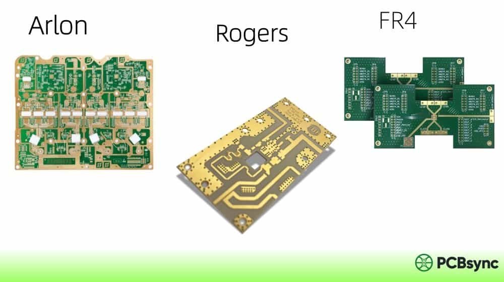
If you’ve ever wrestled with the age-old dilemma of choosing between affordable FR-4 and high-performance Rogers materials for your wireless designs, you’re not alone. For years, RF engineers have faced an uncomfortable gap: FR-4 loses its charm above 2-3 GHz, but jumping to RO4003C or RO4350B often blows the budget for cost-sensitive consumer applications.
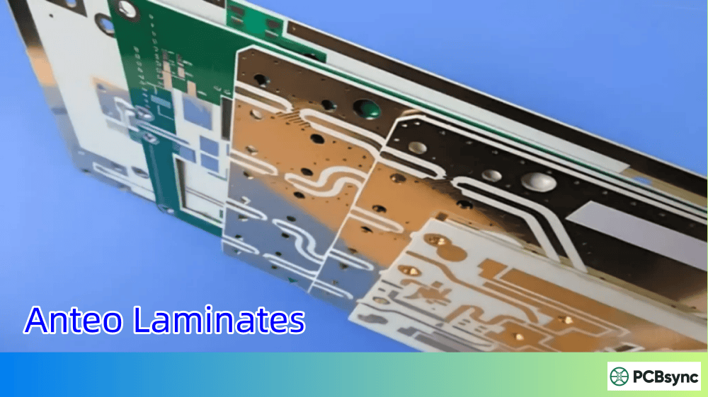
Enter Anteo laminates—Rogers Corporation’s answer to this material selection headache. Launched in 2023, this glass-reinforced hydrocarbon ceramic laminate family sits squarely in the sweet spot between standard FR-4 and premium RF materials. In this guide, I’ll walk you through everything you need to know about Anteo laminates, from specifications and applications to fabrication considerations and where they fit in the Rogers product lineup.
Anteo laminates are a cost-effective, glass-reinforced hydrocarbon ceramic system engineered specifically for high-frequency applications where FR-4 falls short but premium RF materials seem like overkill.
Here’s what makes them unique: Rogers designed the dielectric constant (Dk) to align with FR-4 industry standards. This means you can transition existing FR-4 designs to Anteo with minimal re-engineering while gaining significant improvements in loss performance.
The key selling point? Standard FR-4 fabrication processes. Your PCB fabricator doesn’t need special equipment or exotic processing procedures. If they can build FR-4 boards, they can build Anteo boards. This keeps manufacturing costs down and lead times reasonable.
Key Material Characteristics
Anteo belongs to Rogers’ thermoset hydrocarbon platform—the same technology backbone behind the popular RO4000 series. However, it’s specifically formulated to offer:
FR-4-like dielectric constant for design compatibility
Lower loss than standard FR-4 at high frequencies
Tighter Dk and thickness tolerances than typical FR-4
UL 94 V-0 flame retardant rating
Lead-free process compatibility
Anteo Laminates Technical Specifications
Understanding the numbers behind Anteo laminates helps you determine if they’re right for your application. Here’s the complete specification breakdown based on the official Rogers datasheet:
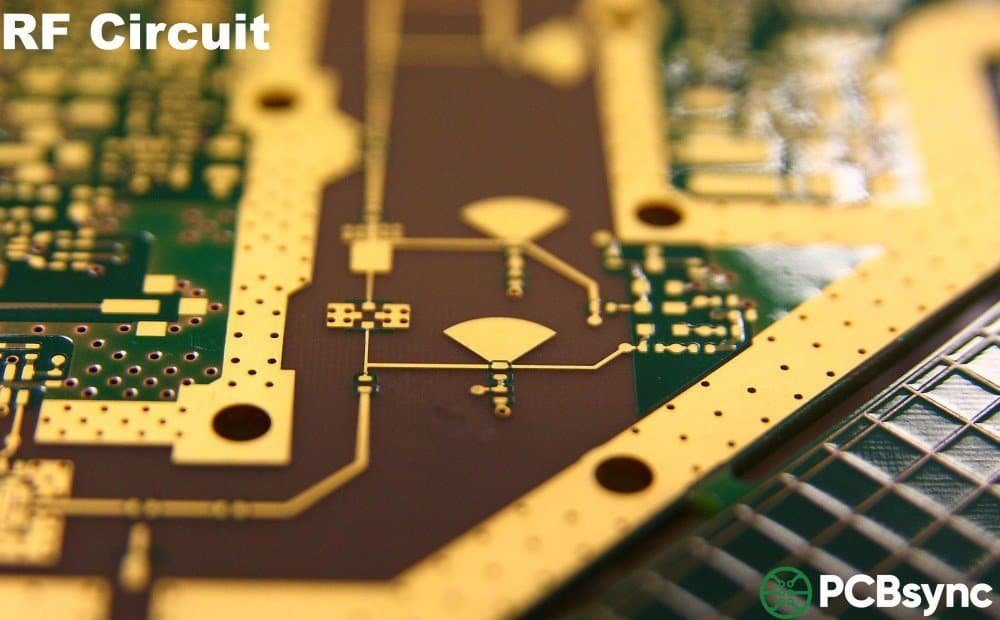
The dissipation factor of 0.005 at 10 GHz is the standout number here. Compare that to standard FR-4’s typical Df of 0.02-0.025 at 10 GHz—Anteo offers roughly 4-5x improvement in loss performance. For antenna and RF front-end designs, this translates directly to better efficiency and range.
Thermal Properties
Property
Value
Test Conditions
Test Method
Decomposition Temperature (Td)
414°C
5% weight loss
IPC TM-650 2.3.40
CTE (X-axis)
13 ppm/°C
-55°C to 288°C
IPC TM-650 2.4.41
CTE (Y-axis)
16 ppm/°C
-55°C to 288°C
IPC TM-650 2.4.41
CTE (Z-axis)
42 ppm/°C
-55°C to 288°C
IPC TM-650 2.4.41
Thermal Conductivity
0.64 W/(m·K)
80°C
ASTM D5470
Time to Delamination
>60 minutes
288°C, as-received
IPC TM-650 2.4.24.1
The low Z-axis CTE of 42 ppm/°C is particularly noteworthy. Standard FR-4 typically runs 50-70 ppm/°C in the Z-axis, which can stress plated through-holes during thermal cycling. Anteo’s lower expansion improves PTH reliability in automated assembly environments.
Mechanical and Physical Properties
Property
Value
Test Method
Copper Peel Strength
5.3 N/mm
IPC TM-650 2.4.8
Tensile Strength (MD/CMD)
16/12 kpsi
ASTM D3039
Flexural Strength (MD/CMD)
25/19 kpsi
IPC-TM-650 2.4.4
Flammability Rating
UL 94 V-0
UL 94
Moisture Absorption
0.07%
IPC TM-650 2.6.2.1
That 0.07% moisture absorption figure is excellent—much lower than FR-4’s typical 0.1-0.3%. In humid environments or outdoor applications, lower moisture uptake means more stable electrical performance over time.
Standard Anteo Laminate Offerings
Rogers offers Anteo in configurations that cover most common PCB design requirements:
Available Thicknesses
Thickness (inches)
Thickness (mm)
Tolerance
0.020″
0.508 mm
±0.0015″
0.030″
0.762 mm
±0.002″
0.040″
1.016 mm
±0.003″
0.060″
1.524 mm
±0.004″
0.090″
2.286 mm
±0.004″
0.120″
3.048 mm
±0.006″
Panel Sizes
24″ × 18″ (610 × 457 mm)
24.25″ × 18.25″ (616 × 464 mm)
48″ × 36″ (1219 × 915 mm)
48.25″ × 36.25″ (1226 × 921 mm)
Copper Cladding Options
½ oz (18 µm) HH/HH electrodeposited copper
1 oz (35 µm) H1/H1 electrodeposited copper
Additional configurations are available through Rogers customer service for specific project requirements.
Anteo Laminates vs FR-4: Why Make the Switch?
Let’s get practical. When should you consider Anteo over standard FR-4? The answer depends on your operating frequency, performance requirements, and cost constraints.
Performance Comparison
Parameter
Standard FR-4
Anteo L43
Improvement
Dk @ 10 GHz
4.2-4.7 (varies)
4.38 ±0.05
Tighter tolerance
Df @ 10 GHz
0.020-0.025
0.005
4-5× lower loss
Dk Tolerance
±0.3 typical
±0.05
6× tighter
Thickness Tolerance
±10% typical
±3-5%
2-3× tighter
Z-axis CTE
50-70 ppm/°C
42 ppm/°C
Better PTH reliability
Moisture Absorption
0.1-0.3%
0.07%
30-75% lower
When FR-4 Works Fine
For applications below 1-2 GHz with short trace lengths, standard FR-4 remains perfectly adequate. Consumer electronics, low-speed digital circuits, and non-critical RF paths don’t need the performance premium of Anteo.
When Anteo Makes Sense
Consider Anteo laminates when you encounter any of these scenarios:
Frequency creep: Your design operates in the 2-6 GHz range where FR-4’s losses become noticeable but premium RO4000 series materials seem excessive.
Efficiency matters: For battery-powered wireless devices, every dB of insertion loss you save extends battery life. GPS receivers, WiFi modules, and IoT sensors fall into this category.
Tolerance frustration: You’re tired of the Dk variation in FR-4 batches causing impedance inconsistency between production runs.
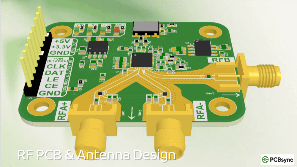
Antenna performance: Antenna gain and efficiency directly suffer from substrate losses. Switching from FR-4 to Anteo can improve antenna performance without a complete redesign.
Anteo fills the gap between commodity FR-4 and the RO4000 series. If you’ve been using FR-4 and hitting its limits, Anteo is the logical first step up. If RO4003C or RO4350B are stretching your budget for high-volume consumer products, Anteo offers a more economical alternative with respectable performance.
Design Transition Considerations
One of Anteo’s strongest selling points is Dk alignment with FR-4 standards. The 4.38 dielectric constant means:
Existing FR-4 trace width calculations remain approximately valid
Impedance recalculation is straightforward
You can often reuse FR-4 stackup designs with minor adjustments
Design tools already calibrated for FR-4 need minimal changes
This contrasts with transitioning to RO4003C (Dk 3.38) or RO4350B (Dk 3.48), which typically requires significant trace geometry changes due to the lower dielectric constant.
Target Applications for Anteo Laminates
Rogers specifically positions Anteo laminates for wireless applications that have outgrown FR-4 but don’t require premium RF material performance. Based on the official documentation and application notes, key target markets include:
GPS Antennas
Global positioning system antennas operate in the 1.2-1.6 GHz L-band range. While FR-4 can work at these frequencies, the tighter Dk tolerance and lower loss of Anteo improve antenna efficiency and receiver sensitivity—critical for handheld and battery-powered GPS devices.
WiFi Antennas
Modern WiFi spans 2.4 GHz (802.11b/g/n) through 5-6 GHz (802.11a/n/ac/ax) and increasingly WiFi 6E at 6 GHz. This frequency range pushes FR-4 to its limits, particularly for the 5-6 GHz bands. Anteo’s 4× improvement in dissipation factor directly improves antenna efficiency and range.
V2X Communications
Vehicle-to-Vehicle (V2V) and Vehicle-to-Infrastructure (V2I) systems—collectively V2X—operate in the 5.9 GHz band (DSRC) or use cellular V2X (C-V2X) technology. The automotive industry demands cost-effective solutions for high-volume production. Anteo addresses this by offering RF-grade performance at a price point suitable for automotive volumes.
IoT Segments
The Internet of Things encompasses countless wireless applications: smart home devices, wireless meters, industrial sensors, and asset trackers. Many of these devices are cost-sensitive but require reliable wireless performance. Anteo’s combination of respectable RF performance and FR-4-like fabrication costs makes it attractive for IoT hardware manufacturers.
Fabrication Guidelines for Anteo Laminates
One of Anteo’s key advantages is compatibility with standard FR-4 processing procedures. If your fabricator builds FR-4 boards, they can build Anteo boards without significant process changes.
Processing Compatibility
According to Rogers’ fabrication guidelines, Anteo shares processing parameters with the established RO4003C, RO4350B, and RO4835 materials:
Drilling: Use standard entry and exit materials. Carbide tools with surface speeds below 500 SFM maximize tool life. Chip loads greater than 0.002″/rev work well for mid-range and large diameter tools.
Routing: Carbide multi-fluted spiral chip breakers or diamond-cut router bits perform well. Maximum stack height should be 70% of actual flute length for debris removal.
Plating: Compatible with electroless copper processing and standard acid copper plating. No special treatments required before metallization.
Etching: Standard strip/etch/strip processes work fine. Preserve the post-etch surface for optimal bondply adhesion.
Multilayer: Compatible with many thermosetting and thermoplastic adhesive systems. Consult adhesive manufacturer guidelines for specific bond cycle parameters.
What to Avoid
Rogers recommends against etchback of Anteo laminate layers. Aggressive etchback can loosen filler particles on hole walls and damage resin near copper layers.
Lead-Free Soldering
Anteo laminates are lead-free process compatible—an increasingly important requirement as regulatory pressure eliminates leaded solder from commercial electronics. The material withstands Pb-free reflow temperatures without delamination or degradation.
Compliance and Certifications
For design engineers working on products with regulatory requirements, Anteo’s certifications matter:
Rogers distributes RF Solutions materials through regional partners:
US and Canada: International Electronic Components (IEC)
Europe (except Spain and Italy): CCI Eurolam
Contact Rogers directly or visit the regional distributor websites for pricing and availability.
Frequently Asked Questions
What is the main difference between Anteo laminates and RO4003C?
Anteo has a higher dielectric constant (4.38 vs 3.38) that matches FR-4, making design transitions simpler. RO4003C offers lower loss (Df 0.0027 vs 0.005) and lower Dk for applications requiring maximum RF performance. Anteo is positioned as a cost-effective FR-4 upgrade, while RO4003C serves premium RF applications.
Can I use standard FR-4 fabrication processes for Anteo laminates?
Yes. Rogers designed Anteo to be processed using standard epoxy/glass (FR-4) procedures. Your fabricator doesn’t need special equipment or exotic processing techniques. This compatibility keeps manufacturing costs down compared to PTFE-based materials.
What frequencies are Anteo laminates suitable for?
Anteo performs well from sub-GHz through approximately 10 GHz, making it suitable for GPS (1.2-1.6 GHz), cellular (600 MHz-6 GHz), WiFi (2.4-6 GHz), and V2X (5.9 GHz) applications. For millimeter-wave applications above 10 GHz, consider RO3000 or RT/duroid series materials.
Is Anteo compatible with lead-free soldering?
Yes. Anteo laminates are fully compatible with lead-free solder processes and can withstand Pb-free reflow temperatures (typically 260°C peak) without delamination. This meets RoHS compliance requirements for commercial electronics.
How does Anteo compare to FR-4 on cost?
Anteo costs more than commodity FR-4 but significantly less than RO4003C or RO4350B. The exact price difference depends on volume, thickness, and copper weight. However, because Anteo uses standard FR-4 fabrication processes, the manufacturing cost premium is lower than for PTFE-based materials that require specialized handling.
Design Tips: Getting the Most from Anteo Laminates
Based on my experience working with hydrocarbon ceramic materials, here are some practical tips for designing with Anteo:
Stack-Up Considerations
Since Anteo’s Dk closely matches FR-4, you can often adapt existing FR-4 stack-ups with minimal changes. However, pay attention to:
Mixed-material builds: Anteo works well in hybrid stack-ups where RF layers use Anteo while non-critical layers use lower-cost FR-4 prepreg. This optimizes cost while delivering RF performance where it matters.
Impedance calculations: Use the design Dk value (4.38) for impedance calculations. The tighter tolerance compared to FR-4 means less impedance variation between production lots.
Thermal considerations: With thermal conductivity of 0.64 W/(m·K)—roughly double standard FR-4—Anteo provides modest improvement in heat spreading for power amplifier applications.
Trace Width Guidelines
For a 50Ω microstrip on 20mil (0.508mm) Anteo with Dk = 4.38:
Approximate trace width: 36-38 mils (0.91-0.97mm)
These values are similar to FR-4 designs, simplifying migration
Always verify with your preferred impedance calculator using actual laminate thickness and copper weight for production designs.
Antenna Design Notes
For patch antennas, the higher Dk of Anteo (compared to RO4003C) means smaller physical dimensions for a given frequency—a potential advantage where board space is limited. However, bandwidth may be slightly narrower. Evaluate this tradeoff based on your specific application requirements.
Final Thoughts
Anteo laminates fill a real gap in the PCB material market. For years, RF engineers faced a frustrating choice: accept FR-4’s limitations or pay a significant premium for RO4000 series materials. Anteo provides a middle ground—meaningful performance improvements over FR-4 at a price point that works for cost-sensitive wireless applications.
If you’re designing GPS antennas, WiFi radios, V2X systems, or IoT devices and finding FR-4’s loss performance inadequate, Anteo deserves serious consideration. The FR-4-compatible Dk simplifies design transitions, standard fabrication processes keep costs reasonable, and the 4× improvement in dissipation factor delivers measurable performance gains.
For applications demanding the absolute lowest loss or operation into millimeter-wave frequencies, RO4003C, RO4350B, or RT/duroid materials remain the better choice. But for the vast middle ground of commercial wireless applications, Anteo laminates hit a compelling sweet spot of performance and economics.
Inquire: Call 0086-755-23203480, or reach out via the form below/your sales contact to discuss our design, manufacturing, and assembly capabilities.
Quote: Email your PCB files to Sales@pcbsync.com (Preferred for large files) or submit online. We will contact you promptly. Please ensure your email is correct.
Notes: For PCB fabrication, we require PCB design file in Gerber RS-274X format (most preferred), *.PCB/DDB (Protel, inform your program version) format or *.BRD (Eagle) format. For PCB assembly, we require PCB design file in above mentioned format, drilling file and BOM. Click to download BOM template To avoid file missing, please include all files into one folder and compress it into .zip or .rar format.


