Inquire: Call 0086-755-23203480, or reach out via the form below/your sales contact to discuss our design, manufacturing, and assembly capabilities.
Quote: Email your PCB files to Sales@pcbsync.com (Preferred for large files) or submit online. We will contact you promptly. Please ensure your email is correct.
Notes: For PCB fabrication, we require PCB design file in Gerber RS-274X format (most preferred), *.PCB/DDB (Protel, inform your program version) format or *.BRD (Eagle) format. For PCB assembly, we require PCB design file in above mentioned format, drilling file and BOM. Click to download BOM template To avoid file missing, please include all files into one folder and compress it into .zip or .rar format.
I’ve been designing PCBs for over a decade, and if there’s one thing that’s changed dramatically in recent years, it’s how we approach traceability. Back in the day, we’d slap a simple date code on a board and call it good. Now? PCB QR codes have become essential for any serious manufacturing operation.
Whether you’re trying to track boards through production, link to documentation, or meet IPC-1782 compliance requirements, understanding how to properly implement QR codes on your circuit boards is no longer optional—it’s a competitive necessity.
In this guide, I’ll walk you through everything I’ve learned about PCB QR code implementation: from choosing between QR and Data Matrix codes, to the nitty-gritty of size requirements and placement strategies, to step-by-step tutorials for adding codes in KiCad and Altium.
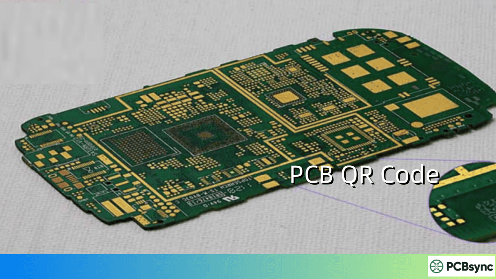
A PCB QR code is a two-dimensional barcode applied to a printed circuit board that stores encoded information. Unlike traditional 1D barcodes that hold limited data in a linear format, QR codes store information both horizontally and vertically, allowing them to pack significantly more data into a smaller footprint.
The “QR” stands for “Quick Response”—and that name isn’t just marketing. These codes were originally developed by Denso Wave in 1994 for tracking automotive parts, and they’ve since become the standard for consumer-facing applications where fast scanning matters.
High data capacity: A single QR code can store up to 4,296 alphanumeric characters or 7,089 numeric digits. That’s enough for serial numbers, URLs, manufacturing dates, and more—all in one compact symbol.
Error correction built-in: QR codes use Reed-Solomon error correction, meaning they remain scannable even when partially damaged. Depending on the error correction level chosen, up to 30% of the code can be obscured and still scan successfully.
Universal readability: Any modern smartphone can scan a QR code without specialized equipment. This makes QR codes ideal for end-user applications like linking to documentation, warranty registration, or firmware downloads.
Omnidirectional scanning: Unlike 1D barcodes that require specific alignment, QR codes can be read from any angle—a significant advantage on crowded production lines.
PCB QR Code vs Data Matrix: Which Should You Use?
This is probably the most common question I get from engineers new to 2D coding. Both QR codes and Data Matrix codes are 2D barcodes, but they serve different purposes in the PCB world.
Comparison Table: QR Code vs Data Matrix for PCB Applications
Feature
QR Code
Data Matrix
Typical Size
6mm × 6mm minimum
Can be as small as 1mm × 1mm
Data Capacity
Up to 4,296 alphanumeric
Up to 2,335 alphanumeric
Primary Use
Consumer-facing applications
Internal traceability
Industry Standard
General purpose
ECIA recommended for components
Readability
Smartphone-friendly
Often requires industrial scanners
Space Efficiency
Less efficient
More efficient for small spaces
Error Correction
Up to 30%
Up to 30%
When to Choose QR Codes
Use QR codes when:
End users need to scan the board (linking to documentation, support portals, or firmware)
The application is consumer-facing (IoT devices, maker projects, commercial products)
Smartphone scanning is expected
You have adequate space (minimum 6mm × 6mm recommended)
When to Choose Data Matrix
Use Data Matrix when:
Space is extremely limited (can work in areas as small as 1.5mm × 1.5mm with laser marking)
The code is for internal manufacturing traceability only
You’re working in aerospace, automotive, or medical device industries (where Data Matrix is often the required standard)
ECIA compliance is required for component labeling
The Electronic Components Industry Association (ECIA) specifically recommends Data Matrix for labeling small electronic components, and GS1 has approved Data Matrix as the only 2D code for regulated healthcare items.
Getting the size right is critical. Too small and your code won’t scan reliably. Too large and you’re wasting valuable board real estate.
Minimum Size Guidelines for PCB QR Codes
Application
Minimum Size
Recommended Size
Notes
Smartphone scanning
8mm × 8mm
10mm × 10mm
Standard white legend on green mask
Industrial scanner
6mm × 6mm
8mm × 8mm
High-contrast printing required
Laser marking
5mm × 5mm
6mm × 6mm
Requires quality laser equipment
Short URLs only
5mm × 5mm
6mm × 6mm
Fewer characters = smaller code
Complex data
10mm × 10mm
12mm × 12mm
More data requires larger size
Factors That Affect Scanability
URL length matters more than you think. The complexity of a QR code increases with the data encoded. A short URL like bit.ly/abc123 creates a much simpler code than https://www.yourcompany.com/products/pcb-documentation/board-v2.1-rev3. Whenever possible, use URL shorteners to reduce code complexity.
For most PCB applications, Level M provides the best balance between size and reliability.
Quiet zone requirements. Always maintain a margin of at least 10-20% of the code size around the QR code. JLC PCB and other manufacturers recommend solid blocks designed as 5×5mm, 8×8mm, or 10×10mm in the silkscreen layer.
PCB QR Code Marking Methods
There are several ways to apply QR codes to PCBs, each with distinct advantages and tradeoffs.
1. Silkscreen Printing
How it works: The QR code is printed during the standard silkscreen process using white epoxy ink over the solder mask.
Fixed at time of PCB fabrication (no serialization)
Best for: Static QR codes linking to documentation, company websites, or version information.
2. Laser Marking/Engraving
How it works: A focused laser beam alters or removes the solder mask surface to create permanent marks. Common laser types include fiber lasers, CO2 lasers, and UV lasers.
Pros:
Extremely durable (permanent marking)
High precision (can achieve 1.5mm × 1.5mm codes)
Supports dynamic serialization in production
Environmentally friendly (no consumables)
Cons:
Requires specialized equipment
Higher per-unit cost for low volumes
May need white background block for optimal contrast
Best for: Serial numbers, lot codes, and any application requiring unique identification per board.
3. Inkjet Printing (Direct Legend Printing)
How it works: Industrial inkjet printers apply ink directly to the PCB surface, similar to how your home printer works but with specialized UV-curable inks.
Pros:
High resolution and flexibility
Easy to implement dynamic/variable data
Lower tooling costs than silkscreen
Cons:
Less durable than laser marking
May require protective coating
Quality varies by equipment
Best for: Prototypes, low-volume production, or applications requiring frequent design changes.
4. Polyimide Labels
How it works: Pre-printed high-temperature labels are applied to the PCB, typically by pick-and-place equipment.
Click Create a new footprint using the Footprint Wizard
Select “2D Barcode QRCode” from the wizard list
Enter your data (URL, text, etc.)
Set the pixel size (0.5mm recommended for readable codes)
Choose error correction level (M is typically sufficient)
Generate and place the footprint on your board
Method 2: Using the Image Converter (Any KiCad Version)
This method works with any image, giving you more control over the source:
Generate your QR code using a free online generator (I recommend qr-code-generator.com or goqr.me)
Download as PNG with high resolution
Open Image Converter from the KiCad home screen
Click Load Bitmap and select your QR code image
Set the on-PCB size (8.5mm × 8.5mm minimum for smartphone scanning)
Select Footprint as the Output Format
Choose your board layer (typically Front Silkscreen)
Click Export to Clipboard
In PCB Editor, select Edit → Paste to place the footprint
Move and position as needed
Pro tip: Remove the “https://www.” prefix from your URLs when possible—smartphones handle this automatically, and the shorter URL creates a less complex (and smaller) QR code.
How to Add a QR Code in Altium Designer
Altium Designer versions prior to 25 didn’t have native QR code support, but there are reliable workarounds.
For Altium Designer 25+
Altium now includes native 2D barcode generation. Use the barcode placement tool directly within the PCB editor.
For Earlier Versions: Using the Smart Grid Insert Method
A popular approach uses the Smart Grid Insert feature with external QR generation:
Generate your QR code using an online tool (ensure you’re working in millimeters in Altium)
Open the PCB List window (Shift+F12)
Ensure the window is in Edit mode (click “view” to toggle if needed)
Right-click and select “Smart Grid Insert” or press Ctrl+Ins
Click “Automatic Determine Paste” to import clipboard data
Click OK to place the QR code
The QR code will be composed of multiple fill elements. Select all elements and create a union so you can move the code as a single object.
PCB QR Code Placement Guidelines
Where you put the code matters almost as much as the code itself.
Recommended Placement Strategies
Component side (top layer):
Most accessible for scanning during assembly and field service
Higher visibility but competes with components for space
Best for end-user facing products
Non-component side (bottom layer):
Generally more space available
May be obscured in final assembly (enclosures, mounting)
Good for manufacturing traceability that doesn’t need field access
Placement Don’ts
Don’t place over vias – the via holes can disrupt the code pattern
Don’t overlap with laser marking areas – coordinate with your fab house
Don’t place near high-heat components – thermal stress can degrade the marking
Don’t ignore the quiet zone – maintain clear space around the code
Color Contrast Considerations
For best scannability:
Solder Mask Color
Recommended Code Color
Notes
Green
White (standard)
Proven combination
Black
White (may need label)
Lower contrast, test carefully
White
Black
Invert the code
Blue
White
Good contrast
Red
White
Good contrast
Important: If your solder mask is dark (green, blue, black, red), the QR code must be light-colored (white silkscreen) for scanners to read it. If using white solder mask, invert the code to use dark ink.
PCB Traceability with QR Codes: Meeting IPC-1782
The IPC-1782 standard has become the benchmark for electronics manufacturing traceability. Understanding how QR codes fit into this framework is essential for compliance.
IPC-1782 Traceability Levels
The standard defines four levels of material traceability (M1-M4) and four levels of process traceability (P1-P4):
Level
Description
Typical Application
Level 1
Basic lot/batch tracking
Consumer electronics
Level 2
Individual PCB serial numbers
Commercial products
Level 3
Component-level tracking
Medical devices, aerospace
Level 4
Comprehensive genealogy
Safety-critical systems
What to Encode in Your PCB QR Code
For IPC-1782 compliance, consider encoding:
Serial number – Unique identifier for each board
Date code – Manufacturing date (YYWW format typical)
Lot/batch number – Links to material records
Part number and revision – Design identification
Manufacturer code – UL identifier or company code
Many manufacturers encode a URL that links to a database containing this information, rather than encoding all data directly in the code. This approach allows for:
Smaller QR codes (shorter URLs)
Dynamic data updates without changing the physical code
Extended information access (test results, assembly history, etc.)
Too small: Increase to at least 8mm × 8mm for smartphone scanning
Poor contrast: Ensure white-on-dark or dark-on-white scheme
Insufficient quiet zone: Add 10-20% margin around code
URL too long: Use a URL shortener
Wrong polarity: Invert the code if solder mask is white
Problem: Code Scans But Link Is Broken
Solutions:
Use permanent redirect URLs (bit.ly, tinyurl)
Host QR landing pages on stable domains
Consider encoding static data rather than URLs
Problem: Code Degrades Over Time
Solutions:
Switch to laser marking for permanent codes
Apply conformal coating over inkjet-printed codes
Use higher error correction level (Q or H)
Frequently Asked Questions About PCB QR Codes
What is the minimum size for a PCB QR code?
The practical minimum depends on your application. For smartphone scanning on white silkscreen over green solder mask, 8mm × 8mm works reliably. Industrial scanners can read codes as small as 5mm × 5mm. With laser marking and specialized equipment, codes down to 1.5mm × 1.5mm are achievable, though these typically require dedicated barcode scanners rather than smartphones.
Can QR codes be read on any color solder mask?
Yes, but contrast matters. The standard combination is white silkscreen on green solder mask. For dark masks (black, blue, red), white codes work well. For white solder mask, you’ll need to invert the code to print in dark ink. Always test your specific color combination before committing to production.
What’s the difference between QR code and barcode for PCB marking?
Traditional 1D barcodes (like Code 128) store data in a single horizontal line, limiting capacity to about 20 characters. QR codes store data in both dimensions, holding up to 4,296 characters. QR codes also include error correction and can be scanned from any angle. For PCBs, QR codes are preferred when you need more data or smartphone scanning; 1D barcodes may suffice for simple numeric serial numbers in automated environments.
How do I ensure my PCB QR code survives reflow soldering?
The key is choosing the right marking method. Silkscreen printing uses epoxy inks rated for reflow temperatures (typically up to 260°C peak). Laser marking creates permanent surface changes that are unaffected by heat. If using labels, polyimide labels are specifically designed for high-temperature survival (300°C+). Inkjet printing may require protective conformal coating for reflow applications.
Should I use dynamic or static QR codes on my PCBs?
Static codes encode fixed data directly in the code—what you see is what you get. Dynamic codes typically encode a short URL that redirects to changeable content. For manufacturing traceability where each board needs a unique serial number, you’ll need a dynamic generation system (usually laser marking with database integration). For linking to fixed documentation or websites, static codes work fine and can be part of your standard silkscreen.
Conclusion
Implementing PCB QR codes effectively isn’t complicated, but it does require attention to detail. Choose the right code type for your application (QR for consumer-facing, Data Matrix for space-constrained traceability), size it appropriately (8mm minimum for smartphone scanning), select the right marking method for your durability and volume requirements, and place it where it won’t interfere with other board features.
The investment in proper QR code implementation pays dividends throughout the product lifecycle—from streamlined manufacturing and easier field service to improved counterfeit protection and regulatory compliance.
If you’re just getting started with PCB traceability, begin with a simple QR code linking to your product documentation. As your needs grow, you can expand to dynamic serialization and full IPC-1782 compliance. The infrastructure you build now will serve you well as your products and processes mature.
Final Thoughts on PCB QR Code Implementation
After implementing QR codes on hundreds of board designs over the years, I’ve learned that the small details make the biggest difference. Taking an extra few minutes to optimize your URL length, verify your quiet zone margins, and test your codes with multiple scanning devices before committing to production will save you significant headaches down the road.
The trend toward greater traceability in electronics manufacturing isn’t slowing down. Whether you’re building IoT devices, medical equipment, or industrial controls, the expectation for traceable, identifiable boards will only increase. Getting comfortable with PCB QR code implementation now positions you well for the evolving requirements of modern manufacturing.
Remember: start simple, test thoroughly, and scale your traceability system as your production needs grow. A well-implemented QR code system isn’t just about compliance—it’s a competitive advantage that improves quality, reduces costs, and builds customer confidence.
Inquire: Call 0086-755-23203480, or reach out via the form below/your sales contact to discuss our design, manufacturing, and assembly capabilities.
Quote: Email your PCB files to Sales@pcbsync.com (Preferred for large files) or submit online. We will contact you promptly. Please ensure your email is correct.
Notes: For PCB fabrication, we require PCB design file in Gerber RS-274X format (most preferred), *.PCB/DDB (Protel, inform your program version) format or *.BRD (Eagle) format. For PCB assembly, we require PCB design file in above mentioned format, drilling file and BOM. Click to download BOM template To avoid file missing, please include all files into one folder and compress it into .zip or .rar format.


