Inquire: Call 0086-755-23203480, or reach out via the form below/your sales contact to discuss our design, manufacturing, and assembly capabilities.
Quote: Email your PCB files to Sales@pcbsync.com (Preferred for large files) or submit online. We will contact you promptly. Please ensure your email is correct.
Notes: For PCB fabrication, we require PCB design file in Gerber RS-274X format (most preferred), *.PCB/DDB (Protel, inform your program version) format or *.BRD (Eagle) format. For PCB assembly, we require PCB design file in above mentioned format, drilling file and BOM. Click to download BOM template To avoid file missing, please include all files into one folder and compress it into .zip or .rar format.
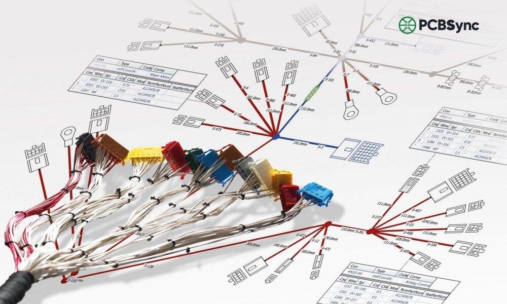
A hands-on engineering guide covering wire harnessing methods, essential tools, industry standards, and proven techniques for professional-quality results.
What Is Wire Harnessing?
Wire harnessing is the process of organizing, bundling, and routing multiple electrical wires and cables into structured assemblies that can be efficiently installed, tested, and maintained. It transforms loose, disorganized wiring into neat, functional units that improve reliability and simplify manufacturing.
Having spent years on factory floors troubleshooting control panels and production equipment, I’ve seen firsthand how proper wire harnessing separates professional installations from problematic ones. Good harnessing isn’t just about appearance—it directly impacts functionality, safety, and serviceability.
The goals of wire harnessing include:
Organization – Grouping related circuits for logical routing
Protection – Shielding wires from physical and environmental damage
Simplification – Enabling faster installation and maintenance
Reliability – Reducing stress, movement, and connection failures
Plastic or polyethylene wrap that spirals around the bundle.
Advantages:
Easy to add/remove wires later
Good abrasion protection
Flexible for routing
Disadvantages:
Can unwind in high-vibration environments
Not suitable for harsh chemicals
Braided Sleeving
Expandable mesh that slides over cables.
Type
Properties
Applications
PET
Lightweight, flexible
Electronics, automotive
Nomex
Flame resistant
Aerospace, military
Kevlar
High abrasion resistance
Industrial, outdoor
Fiberglass
High temperature
Engine compartments
Corrugated Tubing (Split Loom)
Plastic conduit that protects bundles from crushing and abrasion.
Material
Temperature Range
Features
Polypropylene
-40°C to +105°C
General purpose
Polyamide (PA)
-40°C to +120°C
Higher temp, oil resistant
PVDF
-40°C to +150°C
Chemical resistant
Heat Shrink Tubing
Provides environmental sealing and strain relief.
Shrink Ratios:
2:1 – Standard applications
3:1 – More accommodation for irregular shapes
4:1 – Maximum shrinkage for large transitions
Lacing and Tying
Traditional method using waxed cord or tape—still required in aerospace and military applications.
Advantages:
Lightweight
No sharp edges
Allows wire movement without damage
Meets MIL-DTL-81381 requirements
Routing Best Practices
Proper routing prevents many common harness failures.
Bend Radius Rules
Cable Type
Minimum Bend Radius
Standard wire
4× outer diameter (static)
Coaxial cable
6× outer diameter
Shielded multiconductor
8× outer diameter
Continuously flexed
10× outer diameter
Fiber optic
Per manufacturer spec (typically 10-15×)
Routing Guidelines
Do:
Follow natural wire paths
Route along structural members where possible
Provide service loops at terminations
Allow for thermal expansion
Separate power and signal wires
Don’t:
Route over sharp edges
Create stress points at breakouts
Route near heat sources
Create wire traps that prevent removal
Route where foot traffic or maintenance occurs
Segregation Requirements
Circuit Type
Separation Distance
Power (> 50A) from signal
75mm (3″) minimum
AC from DC circuits
50mm (2″) minimum
Shielded from unshielded
25mm (1″) minimum
High frequency from low frequency
Per EMC analysis
Securing Methods
Clamping
Clamp Type
Application
P-Clips
General purpose, single cable
Cushioned Clamps
Vibration environments
Saddle Clamps
Large bundles
Cable Tie Mounts
Flexible, general use
Clamp Spacing Guidelines:
Horizontal runs: 150-300mm (6-12″) intervals
Vertical runs: 100-150mm (4-6″) intervals
At each direction change
Both sides of connectors
IPC/WHMA-A-620: Wire Harnessing Standards
The IPC/WHMA-A-620 standard provides acceptance criteria for wire harnessing workmanship. Understanding this standard is essential for professional-quality work.
Product Classes
Class
Description
Typical Industries
Class 1
General electronic products
Consumer goods, non-critical
Class 2
Dedicated service products
Industrial, telecom, automotive
Class 3
High-performance products
Aerospace, medical, military
Key Workmanship Requirements
Wire Preparation
Attribute
Class 1
Class 2
Class 3
Nicked strands
Some acceptable
Minimal
None acceptable
Scraped insulation
Acceptable if no conductor exposed
Minimal
None acceptable
Clean cut ends
Required
Required
Required
Bundling and Securing
Requirement
All Classes
Bundle not over-tightened
Insulation not deformed
Tie spacing
Per specification or 150mm max
Clamp cushioning
Required for vibration environments
Edge protection
Where wires contact sharp edges
Sleeving and Tubing
Requirement
Specification
Heat shrink centering
Centered over transition
Heat shrink recovery
Fully recovered, no wrinkles
Braided sleeve ends
Terminated or sealed
Spiral wrap overlap
25-50% coverage
Wire Harnessing in Manufacturing
Form Board Assembly
The form board (also called assembly board or pin board) is the foundation of harness manufacturing.
Form Board Types:
Type
Construction
Best For
2D Board
Flat layout on wood/composite
Simple harnesses, prototypes
3D Fixture
Contoured jig
Complex routing, high volume
Digital (CAD-generated)
Printed full-scale template
Quick setup, frequent changes
Form Board Components:
Full-scale layout drawing or template
Routing pegs or posts
Connector holders
Breakout locations marked
Wire identification at each position
Assembly Sequence
A typical wire harnessing sequence in production:
Wire Preparation
Cut wires to length
Strip wire ends
Apply terminals
Initial Routing
Place main trunk wires on board
Route according to drawing
Branching
Create breakouts at specified points
Verify branch lengths
Connector Loading
Insert terminals into housings
Verify pin positions
Install secondary locks
Bundling
Apply ties, tape, or sleeving
Maintain specified spacing
Finishing
Apply labels
Install grommets/boots
Final bundle securing
Testing
Continuity check
Isolation test (if specified)
Visual inspection
Quality Control Checkpoints
Checkpoint
What to Verify
Wire preparation
Strip length, strand condition
Terminal crimp
Height, position, pull force
Connector loading
Correct position, seating
Routing
Per drawing, proper radius
Bundling
Spacing, tightness, appearance
Labeling
Correct, legible, positioned
Electrical
Continuity, isolation
Common Wire Harnessing Mistakes
Learning from common errors improves quality:
Mechanical Issues
Mistake
Consequence
Prevention
Over-tightened ties
Insulation damage, conductor stress
Use appropriate tension
Sharp bend radius
Conductor fatigue, failure
Follow minimum radius rules
Missing edge protection
Insulation abrasion
Use grommets, sleeves at edges
Insufficient strain relief
Connector damage
Proper clamping near connectors
Electrical Issues
Mistake
Consequence
Prevention
Poor crimp
High resistance, intermittent connection
Verify crimp parameters
Wrong terminal
Mismatch, loose fit
Double-check part numbers
Reversed polarity
Equipment damage
Use polarized connectors, verify
No testing
Field failures
100% electrical test
Process Issues
Mistake
Consequence
Prevention
Wrong wire length
Recut, waste
Measure twice, cut once
Missing wires
Incomplete assembly
Use checklists, verification
Wrong label
Installation errors
Verify against drawing
Documentation not updated
Configuration issues
Maintain revision control
Wire Harnessing Safety
Personal Protective Equipment
Hazard
PPE Required
Wire ends, sharp tools
Safety glasses
Solder fumes
Ventilation, fume extraction
Heat guns
Heat-resistant gloves
Chemical cleaners
Gloves, eye protection
Electrical testing
Insulated tools, proper procedures
Workspace Safety
Keep work area organized
Store sharp tools properly when not in use
Maintain adequate lighting
Use anti-static precautions when required
Follow lockout/tagout for live equipment
Useful Resources and Downloads
Industry Standards:
IPC/WHMA-A-620 – Cable and Wire Harness Assemblies – shop.ipc.org
NASA-STD-8739.4 – Crimping, Interconnecting Cables, Harnesses, and Wiring – standards.nasa.gov
MIL-DTL-81381 – Lacing Cord and Tape – everyspec.com
What is the difference between wire harnessing and cable lacing?
Wire harnessing is the general process of bundling wires, using any method (ties, tape, sleeving, lacing). Cable lacing is a specific technique using waxed cord or flat tape, typically required by aerospace and military specifications. Lacing is lighter and allows more wire movement, but requires skilled hand work.
How do I choose between zip ties and spiral wrap?
Factor
Zip Ties
Spiral Wrap
Cost
Lower
Higher
Speed
Faster
Slower
Serviceability
Cut to remove
Easy to unwrap
Flexibility
Rigid points
Continuous flex
Best for
Permanent, simple bundles
Field service, frequent changes
What crimp height should I use?
Crimp height is terminal-specific. Always use the manufacturer’s specification:
Consult terminal data sheet for nominal crimp height
Set up crimp tooling per manufacturer instructions
Crimp sample terminals and measure with micrometer
Adjust until within specified tolerance (typically ±0.05mm)
Document settings for that terminal/wire combination
How often should I replace wire stripping blades?
Replace stripping blades when:
Cuts are no longer clean (ragged edges)
Conductor nicking increases
Adjustment can’t compensate for wear
Blade edges are visibly damaged
For production environments, many shops replace blades on a schedule (e.g., weekly for high-volume, monthly for moderate use) rather than waiting for failures.
What documentation should I maintain for wire harnessing?
Document Type
Content
Purpose
Work Instructions
Step-by-step procedures
Consistent production
Inspection Checklists
Quality verification points
Quality assurance
Training Records
Personnel qualifications
Competency tracking
Tool Calibration
Crimp tool verification
Process control
Nonconformance Reports
Defect documentation
Continuous improvement
Conclusion
Wire harnessing is a fundamental skill that combines attention to detail with practical knowledge of materials, tools, and techniques. Whether you’re building prototypes on the bench or managing production of thousands of harnesses, the principles remain the same: proper planning, correct tools, adherence to standards, and thorough verification.
Key takeaways:
Invest in quality tools appropriate for your work
Learn and follow IPC/WHMA-A-620 workmanship standards
Develop consistent processes and document them
Test every harness before it leaves your hands
Keep learning—wire harnessing techniques continue to evolve
For more detailed information on complete assemblies, explore our guides on wire harness assembly, cable harness assembly, and cable assembly types.
Inquire: Call 0086-755-23203480, or reach out via the form below/your sales contact to discuss our design, manufacturing, and assembly capabilities.
Quote: Email your PCB files to Sales@pcbsync.com (Preferred for large files) or submit online. We will contact you promptly. Please ensure your email is correct.
Notes: For PCB fabrication, we require PCB design file in Gerber RS-274X format (most preferred), *.PCB/DDB (Protel, inform your program version) format or *.BRD (Eagle) format. For PCB assembly, we require PCB design file in above mentioned format, drilling file and BOM. Click to download BOM template To avoid file missing, please include all files into one folder and compress it into .zip or .rar format.


