Inquire: Call 0086-755-23203480, or reach out via the form below/your sales contact to discuss our design, manufacturing, and assembly capabilities.
Quote: Email your PCB files to Sales@pcbsync.com (Preferred for large files) or submit online. We will contact you promptly. Please ensure your email is correct.
Notes: For PCB fabrication, we require PCB design file in Gerber RS-274X format (most preferred), *.PCB/DDB (Protel, inform your program version) format or *.BRD (Eagle) format. For PCB assembly, we require PCB design file in above mentioned format, drilling file and BOM. Click to download BOM template To avoid file missing, please include all files into one folder and compress it into .zip or .rar format.
A comprehensive guide for PCB engineers covering FR5 PCB material properties, specifications, applications, and when to choose FR5 over FR4 for your high-temperature electronic designs.
Introduction to FR5 PCB
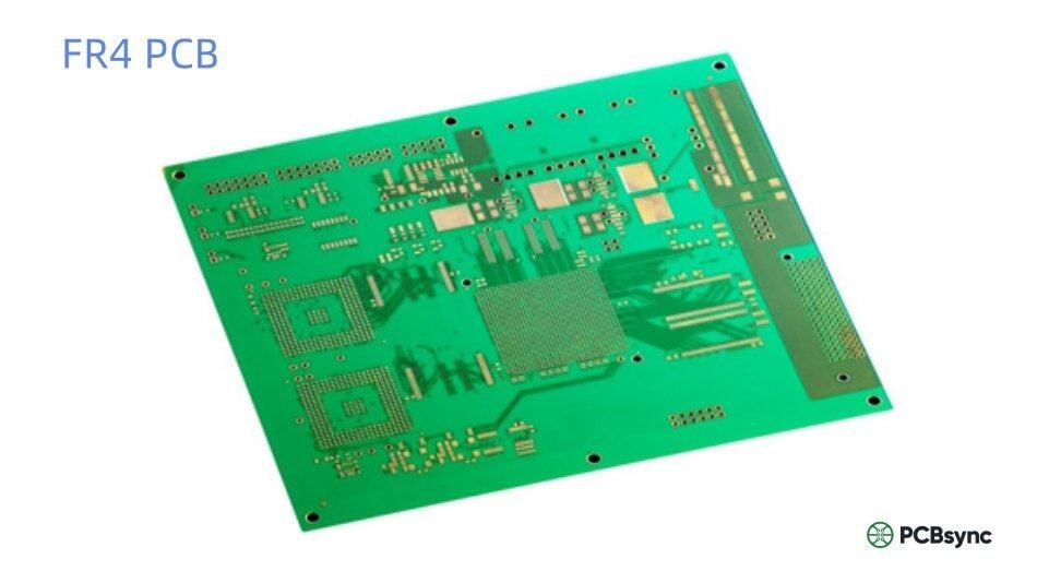
If you’ve been designing PCBs for any length of time, you’ve almost certainly worked with FR4. It’s the workhorse of our industry, showing up in everything from consumer gadgets to industrial controllers. But there are situations where FR4 just doesn’t cut it—and that’s where FR5 PCB material comes into play.
I’ve seen plenty of projects run into thermal issues because the design team stuck with FR4 when they really needed something more robust. The resulting field failures aren’t pretty—delamination, warping, intermittent connections. FR5 exists precisely to handle those demanding applications where standard materials fall short.
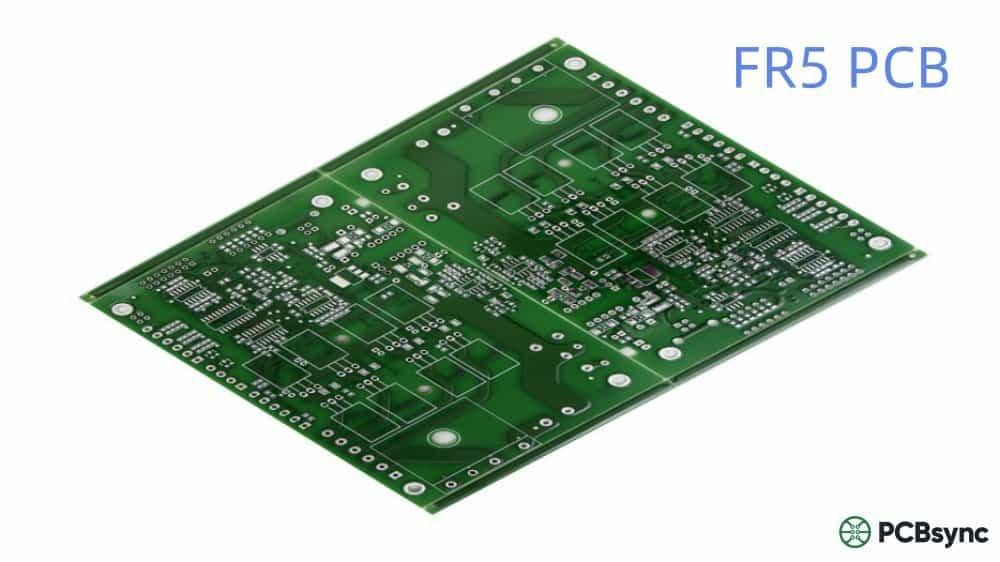
FR5 PCB is a high-performance laminate material made from woven glass fabric reinforced with high-temperature epoxy resin. The “FR” designation stands for “Flame Retardant,” indicating compliance with UL94V-0 flammability standards. What sets FR5 apart from its more common cousin FR4 is its elevated glass transition temperature (Tg) and superior mechanical properties at high temperatures.
The NEMA (National Electrical Manufacturers Association) classification system categorizes flame-retardant laminates from FR-1 through FR-5. Each number represents different material compositions and performance characteristics. FR5 sits at the top of this hierarchy, offering the best combination of thermal stability and mechanical strength.
Material Composition
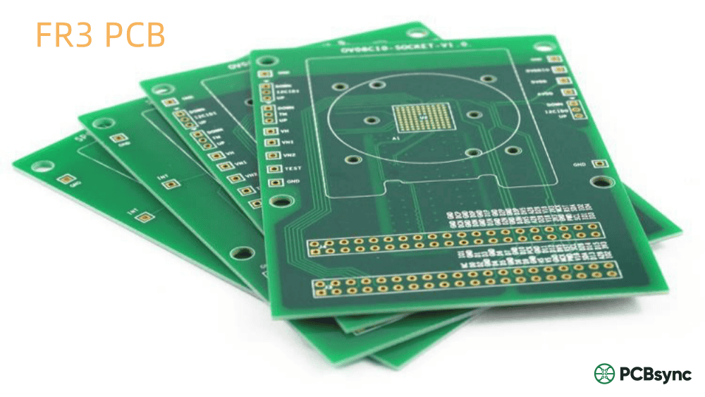
FR5 PCB substrate consists of woven fiberglass cloth impregnated with a high-temperature epoxy resin binder. The natural color typically appears as a yellow-green-tan blend. While this sounds similar to FR4’s composition, the key difference lies in the epoxy resin system—FR5 uses a more advanced formulation that maintains structural integrity at elevated temperatures where FR4 would begin softening.
Think of FR5 as the fire-retardant grade of G11 material. It’s essentially a thermosetting fiberglass composite that’s been optimized for applications demanding both high-temperature performance and flame resistance. The material certifies to NEMA FR5 standards and maintains good properties in both dry and humid conditions.
FR5 PCB Technical Specifications
Here’s where the numbers matter. When you’re specifying materials for a critical application, you need hard data—not marketing fluff. Let me break down the key specifications that make FR5 PCB suitable for demanding environments.
The Tg value represents the temperature at which the material transitions from a rigid, glassy state to a more flexible, rubbery condition. For FR5 PCB, this occurs between 170-180°C—significantly higher than FR4’s typical 130-140°C range. This extra thermal headroom is crucial for lead-free soldering processes and high-temperature operating environments.
Coefficient of Thermal Expansion (CTE)
The CTE tells you how much the material expands when heated. FR5’s lower Z-axis expansion compared to standard FR4 means better reliability in multilayer designs. When you’re stacking 8, 12, or more layers, even small differences in thermal expansion can lead to barrel cracking and via failures during thermal cycling. The smaller Z-CTE of FR5 PCB makes it particularly well-suited for high-layer-count boards.
Moisture Absorption
Moisture is the enemy of PCB reliability. It degrades lamination quality, affects solder mask adhesion, and can reduce the effective Tg of your board. FR5’s near-zero moisture absorption means your boards maintain their specified performance even in humid environments—no derating required.
FR5 PCB vs FR4: A Detailed Comparison
The question I hear most often is: “When should I use FR5 instead of FR4?” It’s a fair question—FR4 handles the vast majority of applications just fine, and it’s significantly cheaper. Let’s look at how these materials stack up against each other.
Property
FR4
FR5
Glass Transition (Tg)
130-140°C
170-180°C
Operating Temperature
Up to 110°C
Up to 140°C
Heat Resistance
Good
Approximately 2x FR4
Z-Axis CTE
Higher
Lower (better for multilayer)
Mechanical Strength at High Temp
Degrades above Tg
Maintains strength
Loss Tangent (Df)
~0.02
Lower (better HF performance)
Lead-Free Soldering
Requires High-Tg variant
Excellent compatibility
Cost
Lower
20-30% higher
Availability
Widely available
Specialized suppliers
Market Share
>90% of rigid PCBs
Niche/specialized
Key Advantages of FR5 PCB Material
Understanding the specific advantages helps you make informed material decisions. Here’s what FR5 PCB brings to the table:
Superior Thermal Performance
The elevated Tg of 170-180°C gives FR5 PCB significantly more thermal headroom than standard FR4. This matters during both manufacturing (lead-free reflow peaks around 250-260°C) and operation (high-power components, enclosed environments). The material maintains its mechanical properties at temperatures where FR4 would start to soften and potentially fail.
Excellent Lead-Free Soldering Compatibility
Lead-free assembly processes run 30-40°C hotter than traditional tin-lead soldering. FR5 PCB handles these elevated temperatures without the delamination risks that plague standard FR4. This makes FR5 an excellent choice for RoHS-compliant manufacturing where thermal stress during assembly is a concern.
Enhanced Mechanical Strength
FR5 offers superior tear strength, flexural strength, and impact resistance compared to FR4. This translates to better performance in applications subject to mechanical stress, vibration, or thermal shock. The material simply holds up better under harsh conditions.
Better High-Frequency Performance
While neither FR4 nor FR5 are ideal for RF applications (you’d want Rogers or similar for that), FR5’s lower loss tangent does provide improved signal integrity at higher frequencies. For designs operating in the hundreds of MHz to low GHz range, FR5 can offer a noticeable improvement over standard FR4.
Ideal for Multilayer Designs
The reduced Z-axis thermal expansion makes FR5 PCB particularly well-suited for high-layer-count boards. When you’re dealing with 10+ layer stackups, the cumulative effect of thermal expansion on via reliability becomes significant. FR5’s lower CTE helps maintain via integrity through multiple thermal cycles.
FR5 PCB finds its home in applications where standard materials can’t meet the performance requirements. Here are the primary industries and use cases where FR5 makes sense:
Automotive Electronics
Under-hood electronics face extreme temperature variations—from cold starts below -40°C to operating temperatures exceeding 125°C. Engine control units (ECUs), powertrain controllers, and sensor interfaces all benefit from FR5’s thermal stability. The automotive industry has increasingly adopted FR5 for these demanding applications.
Aerospace and Defense
Mission-critical aerospace electronics demand the highest reliability. FR5 PCB is commonly specified for avionics, radar systems, satellite communications, and military electronics. The material’s ability to maintain performance under extreme conditions makes it a natural fit for these applications where failure isn’t an option.
Telecommunications Infrastructure
High-speed communication equipment, 5G base stations, and networking gear often operate continuously in challenging thermal environments. FR5’s combination of thermal stability and improved electrical properties supports the reliability requirements of telecommunications infrastructure.
Industrial Control Systems
Factory automation, motor drives, and industrial controllers frequently operate in high-temperature environments with significant vibration and electrical noise. FR5 PCB provides the durability and thermal stability these applications require.
Specialized Applications
Beyond these major categories, FR5 is commonly used for antenna isolators, circuit board holders and fixtures, test boards, and solder frames. These applications often involve repeated thermal cycling or exposure to high temperatures during manufacturing processes.
Application Summary Table
Industry
Typical Applications
Why FR5?
Automotive
ECUs, Sensors, Powertrain
High temp under hood
Aerospace
Avionics, Radar, Satellites
Mission-critical reliability
Military/Defense
Weapons Systems, Comms
Extreme environments
Telecom
5G, Base Stations, Routers
Signal integrity, reliability
Industrial
Motor Drives, PLCs
Thermal + vibration
Medical
Imaging, Diagnostics
Long-term reliability
FR5 PCB Manufacturing Considerations
Working with FR5 PCB requires some awareness of manufacturing differences compared to standard FR4. Here’s what you and your fabricator need to know:
Machining and Drilling
FR5’s higher glass content and hardness can present challenges during drilling and routing. Tool wear may be accelerated, and drill bit selection becomes more critical. Work with your fab house to ensure they have experience with FR5 and appropriate tooling.
Lead-Free Assembly Process
One of FR5’s strengths is its excellent performance during lead-free reflow soldering. The material handles the higher peak temperatures (typically 250-260°C) without the delamination or measling issues that can plague standard FR4. This makes FR5 an excellent choice for RoHS-compliant manufacturing.
Cost Considerations
Expect to pay 20-30% more for FR5 PCB compared to standard FR4. The premium reflects both the more expensive raw materials and the specialized manufacturing processes. However, this cost increase is often justified by the improved reliability and reduced field failure rates in demanding applications.
Supplier Selection
Not all PCB manufacturers stock FR5 material or have experience working with it. When sourcing FR5 PCBs, verify that your supplier has a track record with high-Tg materials and can provide appropriate certifications (NEMA FR5, UL ratings, etc.).
When to Choose FR5 PCB Over FR4
Making the right material choice requires balancing performance requirements against cost constraints. Here’s a practical decision framework:
Choose FR5 PCB when:
Operating temperatures exceed 110°C consistently
Your design uses 8+ layers and reliability is critical
The application involves significant thermal cycling
Lead-free assembly with multiple reflow cycles is required
The end use is aerospace, military, or automotive under-hood
Mechanical stress and vibration are significant concerns
Signal integrity at higher frequencies (>500 MHz) is important
Stick with FR4 when:
Operating temperatures stay below 100°C
Cost is the primary driver
The application is consumer electronics with moderate requirements
Standard reliability levels are acceptable
Layer count is 6 or fewer
Useful Resources and Standards
For those who want to dive deeper into FR5 PCB specifications and related standards, here are some valuable resources:
Industry Standards
NEMA LI 1: The primary standard governing industrial laminated thermosets, including FR5 grade designations
IPC-4101: Specification for Base Materials for Rigid and Multilayer Printed Boards
UL 94: Standard for Safety of Flammability of Plastic Materials (V-0 rating)
IPC (ipc.org): Industry association for PCB standards and training
NEMA (nema.org): Standards organization for electrical manufacturers
UL Product iQ: Database for verifying UL certifications
Material Datasheets
Always request current datasheets from your laminate supplier. Key manufacturers include Isola, Shengyi, Kingboard, and Rogers (though Rogers specializes more in high-frequency materials). Datasheets provide the specific Tg, CTE, Dk, and Df values for the exact material grade you’re specifying.
Frequently Asked Questions About FR5 PCB
1. What does “FR” mean in FR5 PCB?
FR stands for “Flame Retardant.” The designation indicates that the material meets UL94V-0 flammability standards, meaning it will self-extinguish after burning rather than continuing to propagate flames. The number “5” distinguishes this specific grade from other FR materials (FR-1 through FR-4) in the NEMA classification system, with FR5 representing the highest performance level for thermal stability.
2. Can I use FR5 PCB for standard consumer electronics?
Technically yes, but it’s usually overkill. FR5 PCB costs 20-30% more than standard FR4 and offers capabilities that most consumer electronics don’t require. For typical operating temperatures below 100°C and standard reliability requirements, FR4 provides excellent performance at lower cost. Reserve FR5 for applications that genuinely need its enhanced thermal and mechanical properties.
3. Is FR5 compatible with lead-free soldering processes?
Absolutely—this is one of FR5’s key strengths. Lead-free reflow soldering peaks around 250-260°C, which is uncomfortably close to standard FR4’s Tg. FR5’s elevated Tg of 170-180°C provides substantial margin, allowing the material to maintain its structural integrity through multiple lead-free reflow cycles without delamination or warping issues.
4. How do I specify FR5 when ordering PCBs?
When requesting quotes, explicitly specify “FR5” or “NEMA FR5” material in your documentation. Include the required Tg (typically 170°C minimum), any UL certification requirements, and the specific application if relevant. Not all fabricators stock FR5, so verify availability early in your sourcing process. Request material certifications and datasheets to confirm you’re getting genuine FR5 laminate.
5. What’s the price difference between FR4 and FR5?
Expect FR5 PCB to cost roughly 20-30% more than equivalent FR4 boards, though this varies by supplier and volume. The premium reflects both higher raw material costs and potentially longer lead times due to limited stock. For high-reliability applications where field failures are expensive, this premium often represents excellent value—the cost of a warranty return or system downtime typically far exceeds the material cost difference.
Types of FR5 PCB Configurations
FR5 material can be fabricated into various PCB configurations depending on your design requirements. Understanding these options helps you specify the right board type for your application.
Single-Sided FR5 PCB
The simplest configuration places components on one side with copper traces on the opposite side. While less common with FR5 due to the material’s premium pricing, single-sided FR5 PCBs find use in high-temperature applications with straightforward circuit requirements. Test boards and solder frames often use this configuration.
Double-Sided FR5 PCB
Double-sided boards feature copper on both sides with plated through-holes (PTH) connecting the layers. This configuration is popular for LED lighting systems, power electronics, and industrial controls where thermal management is critical. The FR5 substrate provides excellent dimensional stability during the thermal cycling these applications typically experience.
Multilayer FR5 PCB
This is where FR5 really shines. High-layer-count boards (8, 10, 12+ layers) benefit significantly from FR5’s reduced Z-axis thermal expansion. The material maintains tight registration between layers during pcb manufacturing and resists via barrel cracking during thermal cycling in the field. Complex aerospace, telecommunications, and automotive electronics commonly specify multilayer FR5 construction.
Rigid-Flex FR5 PCB
Combining rigid FR5 sections with flexible polyimide interconnects creates boards that can fold or flex during installation while maintaining FR5’s thermal performance in critical circuit areas. This hybrid approach is increasingly popular in compact aerospace and medical devices where space constraints require three-dimensional packaging.
Understanding FR5 PCB Electrical Properties
Beyond mechanical and thermal considerations, FR5’s electrical characteristics deserve attention—particularly for high-frequency and high-speed digital applications.
Dielectric Constant (Dk)
The dielectric constant affects signal propagation speed and controlled impedance calculations. FR5 exhibits a Dk similar to FR4 (typically around 4.2-4.7), which means your impedance calculations and trace widths will be comparable. The key advantage is that FR5’s Dk remains more stable across temperature variations, reducing impedance drift in high-temperature environments.
Loss Tangent (Df or Dissipation Factor)
The loss tangent indicates how much signal energy is absorbed by the dielectric material. FR5 generally offers lower Df values than standard FR4, resulting in reduced signal attenuation—particularly noticeable at frequencies above 500 MHz. While FR5 won’t match specialized high-frequency materials like Rogers laminates, it provides measurably better performance than FR4 for moderately high-frequency applications.
Dielectric Strength
FR5 provides high dielectric strength—the maximum voltage the material can withstand before electrical breakdown occurs. This property ensures reliable insulation between copper layers and is particularly important in power electronics where high voltage differentials exist across the board thickness.
Quality Assurance and Testing for FR5 PCB
Given FR5’s use in critical applications, proper quality assurance is essential. Here’s what to look for when evaluating FR5 PCB suppliers and incoming boards.
Material Certifications
Request documentation confirming the laminate meets NEMA FR5 specifications. Legitimate suppliers should provide certificates of conformance, material traceability, and test reports. UL recognition (typically UL94 V-0 or V-1 rating) should be verifiable through UL’s Product iQ database.
Thermal Testing
For critical applications, consider specifying thermal shock testing or temperature cycling qualification. T288 testing (time to delamination at 288°C) is a good indicator of lead-free soldering robustness. Quality FR5 material should withstand multiple minutes at 288°C without delamination.
IPC Class Requirements
Specify appropriate IPC-A-610 class requirements based on your application. Class 2 covers most industrial and commercial products, while Class 3 is required for high-reliability aerospace and military applications. Your fabricator should maintain IPC certification and provide inspection reports demonstrating compliance.
Common Mistakes When Specifying FR5 PCB
After years of reviewing PCB specifications and troubleshooting field issues, I’ve seen some recurring mistakes when engineers specify FR5 material. Avoiding these pitfalls will save you time and headaches.
Incomplete Material Callouts
Simply writing “FR5” on your fab drawing isn’t sufficient. Specify the minimum Tg, required UL rating, and any specific laminate brands you’ve qualified. Without complete specifications, you may receive material that technically meets the FR5 designation but doesn’t match your performance expectations.
Ignoring Lead Time Implications
FR5 isn’t stocked as widely as FR4. Many fabricators need to special-order the material, adding days or weeks to your lead time. Factor this into your project schedule, especially for prototype builds where quick-turn delivery is often expected.
Over-Specifying for the Application
Not every high-reliability application actually requires FR5. Standard high-Tg FR4 variants (with Tg around 170°C) may provide adequate thermal performance at lower cost. Analyze your actual operating conditions before defaulting to the premium material.
Conclusion
FR5 PCB represents the premium tier of standard laminate materials, offering significantly enhanced thermal performance, mechanical strength, and reliability compared to ubiquitous FR4. While FR4 remains the right choice for the vast majority of PCB applications, FR5 fills an important niche for demanding environments where elevated temperatures, thermal cycling, and long-term reliability are critical concerns.
For PCB engineers working on automotive, aerospace, telecommunications, or industrial applications, understanding when and how to specify FR5 is an essential part of the design toolkit. The material’s higher Tg (170-180°C), superior mechanical properties at elevated temperatures, and excellent lead-free soldering compatibility make it the logical choice when standard FR4 can’t meet your requirements.
Remember that material selection is always a tradeoff. FR5’s enhanced performance comes with higher cost and potentially longer lead times. Make your material choice based on a clear understanding of your application’s actual requirements rather than simply specifying the “best” material available. When FR5’s capabilities are genuinely needed, the modest cost premium is typically a small price to pay for the enhanced reliability and performance it delivers.
Inquire: Call 0086-755-23203480, or reach out via the form below/your sales contact to discuss our design, manufacturing, and assembly capabilities.
Quote: Email your PCB files to Sales@pcbsync.com (Preferred for large files) or submit online. We will contact you promptly. Please ensure your email is correct.
Notes: For PCB fabrication, we require PCB design file in Gerber RS-274X format (most preferred), *.PCB/DDB (Protel, inform your program version) format or *.BRD (Eagle) format. For PCB assembly, we require PCB design file in above mentioned format, drilling file and BOM. Click to download BOM template To avoid file missing, please include all files into one folder and compress it into .zip or .rar format.


