Inquire: Call 0086-755-23203480, or reach out via the form below/your sales contact to discuss our design, manufacturing, and assembly capabilities.
Quote: Email your PCB files to Sales@pcbsync.com (Preferred for large files) or submit online. We will contact you promptly. Please ensure your email is correct.
Notes: For PCB fabrication, we require PCB design file in Gerber RS-274X format (most preferred), *.PCB/DDB (Protel, inform your program version) format or *.BRD (Eagle) format. For PCB assembly, we require PCB design file in above mentioned format, drilling file and BOM. Click to download BOM template To avoid file missing, please include all files into one folder and compress it into .zip or .rar format.
Rogers PCB Materials: Complete Guide to RO4000, RO3000, RT/duroid & All Series Laminates Compared
If you’ve spent any time designing RF circuits or high-frequency PCBs, you’ve probably run into the same question I have countless times: which Rogers material should I actually use? After fifteen years of specifying laminates for everything from automotive radar to satellite communications, I’ve learned that picking the right substrate can make or break your design.
This guide covers every major Rogers laminate series—from the workhorse RO4000 family to specialty materials like MAGTREX and TC Series. I’ll share practical insights on when to use each one, their actual part numbers, and the real-world tradeoffs you need to consider.
What is Rogers PCB?
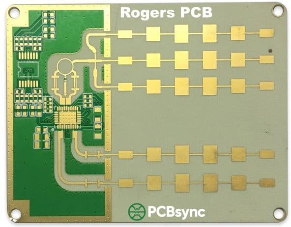
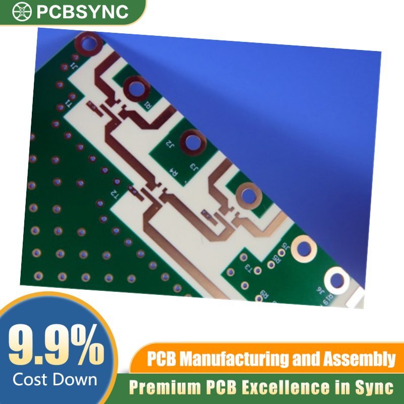
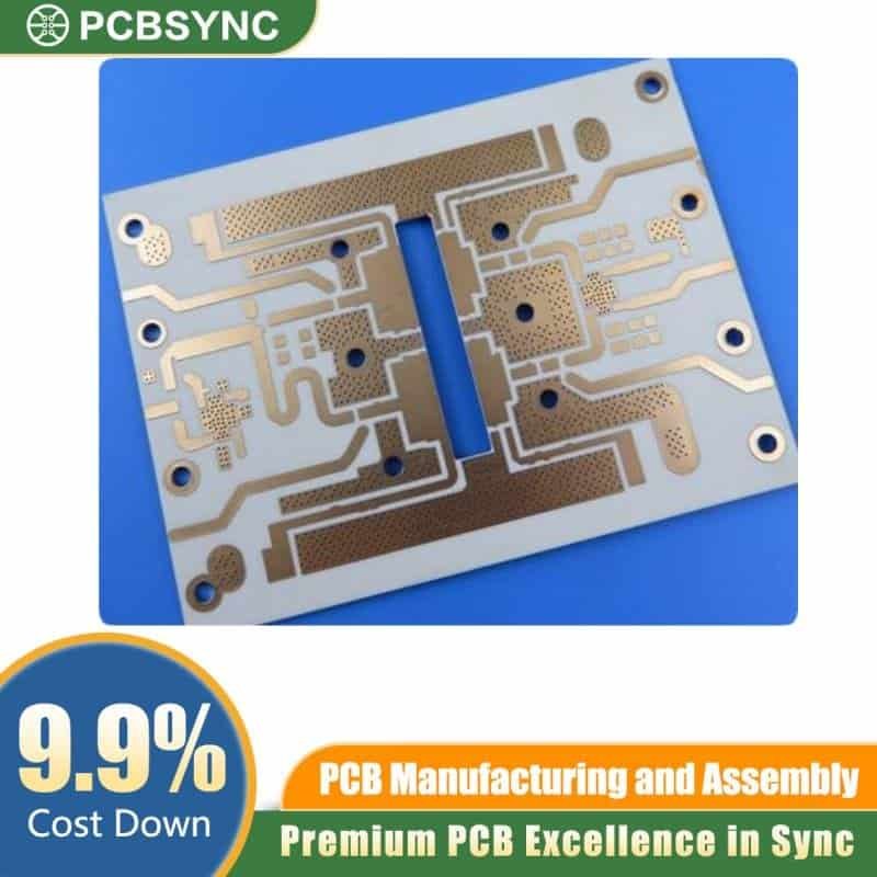
A Rogers PCB is a printed circuit board manufactured using high-frequency pcb laminate materials produced by Rogers Corporation. Unlike standard FR-4 boards that use epoxy resin with woven fiberglass, Rogers PCBs utilize advanced substrate materials—including PTFE (Teflon) composites, ceramic-filled hydrocarbons, and thermoset polymers—specifically engineered for radio frequency (RF), microwave, and high-speed digital applications.
Rogers Corporation, founded in 1832 and headquartered in Chandler, Arizona, has become the industry standard for high-performance PCB substrates. When engineers say “Rogers board” or “Rogers PCB,” they’re referring to circuit boards built on any of Rogers’ specialized laminate materials rather than conventional FR-4.
Low Dielectric Loss: Dissipation factors (Df) as low as 0.0009, compared to FR-4’s typical 0.020. This means significantly less signal energy lost as heat.
Stable Dielectric Constant: The Dk remains consistent across frequency and temperature ranges, ensuring predictable impedance control.
Tight Dk Tolerance: Typical tolerances of ±0.02 to ±0.05, versus FR-4’s ±0.15 or worse. This precision enables tighter design margins.
Low Moisture Absorption: Most Rogers materials absorb less than 0.02% moisture, preventing performance drift in humid environments.
Excellent Thermal Stability: Some materials maintain stable electrical properties from -55°C to +150°C and beyond.
Where Rogers PCBs Are Used
You’ll find Rogers PCBs in virtually every high-frequency application:
Telecommunications: 5G base stations, cellular infrastructure, point-to-point radio links
Industrial: IoT sensors, test equipment, industrial automation
Consumer: GPS devices, Wi-Fi routers, satellite TV receivers
Rogers PCB vs Standard FR-4 PCB
Parameter
Rogers PCB
FR-4 PCB
Dielectric Constant (Dk)
2.2 – 10.2 (varies by material)
4.2 – 4.8
Dk Tolerance
±0.02 to ±0.05
±0.15 or higher
Dissipation Factor (Df)
0.0009 – 0.004
0.018 – 0.025
Frequency Range
DC to 100+ GHz
DC to ~2 GHz optimal
Thermal Conductivity
0.2 – 1.6 W/mK
0.3 W/mK
Moisture Absorption
<0.02%
0.10 – 0.15%
Cost
5x – 20x higher
Baseline
Processing
Some require special treatment
Standard
The cost premium for Rogers materials is substantial, but the performance benefits are essential for any design operating above a few gigahertz. The stable dielectric properties, low loss, and predictable behavior justify the investment when signal integrity matters.
Why Rogers Materials Matter for High-Frequency Design
Standard FR-4 works fine for most consumer electronics. But when you start pushing frequencies above a few GHz, things fall apart quickly. The dielectric constant becomes unstable, losses increase dramatically, and your carefully simulated impedances drift out of spec.
Rogers Corporation has been solving these problems since the 1960s. Their laminates use advanced PTFE composites, ceramic fillers, and hydrocarbon resins to deliver what high-frequency designers actually need: stable dielectric properties, low loss, and predictable performance across temperature and frequency ranges.
The key metrics you’ll care about include:
Dielectric Constant (Dk): Determines trace widths and propagation velocity. Lower Dk means wider traces and faster signals.
Dissipation Factor (Df): Also called loss tangent. Lower is better—it means less signal energy converted to heat.
Thermal Conductivity: Critical for power amplifiers and anything that runs hot.
Coefficient of Thermal Expansion (CTE): Needs to match copper for reliable plated through holes.
Let me walk you through each series and explain where each one shines.
The RO4000 series has become the default choice for most commercial RF applications, and for good reason. These hydrocarbon ceramic laminates offer PTFE-like electrical performance with epoxy/glass processability. That means your fabricator can use standard FR-4 equipment and processes.
RO4000 Series Part Numbers and Specifications
Part Number
Dk (Design)
Df @ 10GHz
Key Feature
Typical Use
RO4003C
3.55
0.0021
Lowest loss, non-brominated
Passive circuits, filters
RO4350B
3.66
0.0031
UL 94 V-0 rated
Power amplifiers, active circuits
RO4360G2
6.40
0.0038
High Dk, compact designs
Size-constrained RF
RO4835
3.66
0.0031
Enhanced oxidation resistance
Automotive radar
RO4835T
3.33
0.0030
Thin cores (2.5-4 mil)
Multilayer builds
RO4533
3.45
0.0025
Spread glass, low skew
High-speed digital
RO4534
3.40
0.0024
Spread glass variant
Antenna arrays
RO4535
3.50
0.0025
Spread glass variant
Combined RF/digital
RO4725JXR
2.55
0.0022
Low Dk antenna grade
Base station antennas
RO4730G3
3.00
0.0027
Hollow-sphere filler
Low PIM antennas
When to Choose RO4000 Series
Use RO4003C when you need the absolute lowest loss and don’t require UL flame ratings. It’s my go-to for filters, couplers, and passive networks where every fraction of a dB matters.
RO4350B is the safer choice for anything with active components or where certification matters. The UL 94 V-0 rating opens doors for commercial and aerospace programs. The slightly higher loss compared to RO4003C rarely matters in practice.
The real advantage of the entire RO4000 family is fabrication cost. Your PCB shop doesn’t need special equipment, plasma treatments, or sodium etch processes. They can drill it, plate it, and etch it just like FR-4. That translates to lower costs and faster turn times.
RO3000 Series: Premium PTFE Performance
When RO4000 isn’t quite good enough, the RO3000 series steps up with ceramic-filled PTFE construction. These materials deliver the lowest losses available in commercial-grade laminates, with dissipation factors as low as 0.0013 at 10 GHz.
What makes RO3000 special is the consistency. The dielectric constant stays rock-solid across temperature and frequency—no step changes, no surprises. This matters when you’re designing filters with tight tolerances or phase-sensitive systems.
The other key feature is the matched CTE across different Dk values. You can use RO3003 on one layer and RO3010 on another without worrying about warpage or delamination. That’s invaluable for complex multilayer designs.
The downside? These are PTFE materials, so your fabricator needs sodium etch or plasma treatment before electroless copper deposition. That adds cost and lead time compared to RO4000.
RT/duroid Laminates: Aerospace-Grade PTFE
The RT/duroid series represents Rogers’ heritage product line—glass microfiber reinforced PTFE composites that have been flying on satellites and missiles for decades. When absolute reliability matters more than cost, this is where you go.
I reach for RT/duroid 5880 when designing space-qualified hardware or millimeter-wave systems. The Df of 0.0009 at 10 GHz is essentially unmatched—it’s as close to lossless as commercial materials get.
The 6000 series (6002, 6006, 6010.2LM) uses ceramic rather than glass microfiber reinforcement. This gives you better thermal conductivity and a wider range of Dk values, but at higher cost.
RT/duroid 6035HTC deserves special mention. With thermal conductivity of 1.44 W/mK, it’s the material of choice when you need both RF performance and heat dissipation. Power amplifier designers love this stuff.
The TMM series bridges the gap between PTFE softness and ceramic brittleness. These thermoset composites won’t soften during soldering or wire bonding, making them ideal for die attach and hybrid circuits.
TMM Series Part Numbers and Specifications
Part Number
Dk (Design)
Df @ 10GHz
TCDk (ppm/°C)
Key Feature
TMM3
3.45
0.0020
+37
Wire bondable, space-qualified
TMM4
4.70
0.0020
+15
Mid-range Dk
TMM6
6.30
0.0023
-11
Negative TCDk
TMM10
9.80
0.0022
-38
High Dk, alumina replacement
TMM10i
9.90
0.0020
-43
Isotropic Dk
TMM13i
12.20
0.0019
-70
Highest Dk thermoset
Why TMM Matters
The thermoset nature of TMM means you can wire bond directly to circuit traces without the substrate deforming. Try that with PTFE and you’ll have problems.
TMM10 and TMM10i are particularly interesting because they can replace alumina ceramic substrates at a fraction of the cost. The Dk is close enough for most designs, but you get the processing flexibility of a polymer-based material.
Space hardware designers appreciate the low TCDk values. When your satellite swings from -150°C in eclipse to +150°C in direct sunlight, you need a substrate that maintains stable electrical properties.
CuClad, DiClad, and IsoClad Series
These PTFE/fiberglass composites offer various tradeoffs between dielectric constant, dimensional stability, and cost.
CuClad’s cross-plied construction provides excellent dimensional stability and isotropy. The 217 variant offers the lowest Dk available in woven glass reinforcement.
IsoClad uses non-woven fiberglass for truly isotropic electrical properties—the Dk is the same regardless of signal direction.
CLTE Series: Low CTE for High Reliability
The CLTE (Controlled Low Thermal Expansion) series addresses the critical problem of via reliability in harsh environments.
CLTE Series Part Numbers
Part Number
Dk
Z-axis CTE
Key Feature
CLTE
3.00
24 ppm/°C
Standard low CTE
CLTE-AT
3.00
24 ppm/°C
Enhanced thermal performance
CLTE-XT
3.00
24 ppm/°C
Extended temperature range
CLTE-MW
3.00
24 ppm/°C
Microwave optimized
When your product goes through repeated thermal cycling—think automotive under-hood electronics or aerospace systems—the mismatch between substrate CTE and copper CTE kills plated through holes. CLTE materials minimize this mismatch.
AD Series: Cost-Effective PTFE
The AD Series provides PTFE performance at lower price points for commercial applications.
The AD series uses similar PTFE/woven glass construction to more expensive materials but with slightly relaxed tolerances. For commercial products where aerospace-grade specs aren’t required, these offer excellent value.
With thermal conductivity 5-8x higher than standard PTFE laminates, TC Series materials keep your power transistors cool while maintaining excellent RF performance. The TC350 Plus variant also features improved drilling characteristics—a real benefit for fabrication.
Specialty Materials
XtremeSpeed RO1200 Series
For high-speed digital backplanes and networking equipment, the RO1200 series offers:
Dk: 3.05 (design)
Df: 0.0017 maximum
CTE matched to copper
UL 94 V-0 rated
Spread glass construction
This is Rogers’ answer to high-speed digital requirements—think 56+ Gbps SerDes channels.
Kappa 438
A glass-reinforced hydrocarbon ceramic system designed as a direct FR-4 replacement:
Dk: 4.38 (aligned with FR-4 standards)
Lower loss than FR-4
Standard FR-4 processing
UL 94 V-0 rated
Kappa 438 is perfect when you need better performance than FR-4 but can’t justify the cost jump to premium RF materials.
MAGTREX 555
The first commercial laminate with controlled permeability and permittivity:
Relative permittivity: 6.5
Relative permeability: 6.0
Enables dramatic antenna size reduction
For antenna designers hitting size constraints, MAGTREX opens new possibilities.
Anteo Laminates
A newer glass-reinforced hydrocarbon ceramic system:
Dk: 4.38 (design)
Df: 0.005 @ 10GHz
FR-4 processing compatible
UL 94 V-0 rated
Anteo provides a cost-effective upgrade path from FR-4 for designs that don’t quite need RO4000-level performance.
IM Series
Extended capabilities for AD and DiClad materials:
Ultra-smooth copper cladding option
Improved insertion loss at high frequencies
Better fine-line etch capability
Radix Printable Dielectric
Rogers’ entry into additive manufacturing:
UV-curable 3D printing resin
Designed specifically for RF applications
Enables rapid prototyping of RF structures
Material Selection Decision Matrix
Choosing the right material involves balancing multiple factors. Here’s my practical decision framework:
By Frequency Range
Frequency
Recommended Materials
< 3 GHz
Kappa 438, Anteo, RO4003C
3-10 GHz
RO4350B, RO4003C, RO3003
10-30 GHz
RT/duroid 5880, RO3003, RO4350B
30-77 GHz
RT/duroid 5880, RO3003
> 77 GHz
RT/duroid 5880, RT/duroid 5870
By Application
Application
Recommended Materials
Automotive radar
RO4835, RO4003C, AD255C
Base station antenna
RO4725JXR, RO4730G3
Satellite communications
RT/duroid 5880, RT/duroid 6002
Power amplifiers
TC350, RO4350B, RT/duroid 6035HTC
High-speed digital
XtremeSpeed RO1200, RO4533
Space-qualified
TMM3, RT/duroid 5880, CLTE-XT
Commercial wireless
Kappa 438, Anteo, RO4003C
By Budget Constraint
Budget Level
Recommended Materials
Entry-level
Kappa 438, Anteo, DiClad 880
Mid-range
RO4003C, RO4350B, AD300D
Premium
RO3003, RT/duroid 5880
Aerospace
RT/duroid 6002, TMM3, CLTE-XT
Fabrication Considerations
Not all Rogers materials process the same way. Here’s what your PCB shop needs to know:
Standard FR-4 Processing
These materials require no special treatments:
RO4000 series (all variants)
Kappa 438
Anteo
XtremeSpeed RO1200
PTFE Processing Required
These materials need sodium etch or plasma treatment:
RO3000 series
RT/duroid series
TMM series
CuClad, DiClad, IsoClad series
CLTE series
AD series
TC series
Drilling Considerations
All Rogers materials can be drilled with standard carbide bits, but:
Ceramic-filled materials (TC series, RO3010, TMM10) cause accelerated tool wear
PTFE materials may require adjusted chip loads
Stack heights and speeds per Rogers’ fabrication guidelines
Frequently Asked Questions
What’s the difference between RO4003C and RO4350B?
Both are hydrocarbon ceramic laminates with similar performance, but RO4350B is UL 94 V-0 rated while RO4003C is halogen-free and not UL rated. Use RO4350B for active circuits or when flammability certification is required; use RO4003C for passive circuits where you need the absolute lowest loss.
Can I replace FR-4 with Rogers materials directly?
Not directly—the different Dk values mean your trace widths and impedances will change. However, Kappa 438 and Anteo are designed with Dk values close to FR-4 to minimize redesign effort. For RO4000 materials, expect to recalculate all controlled-impedance traces.
Which Rogers material has the lowest loss?
RT/duroid 5880 with a Df of 0.0009 at 10 GHz offers the lowest loss of any reinforced laminate. Among hydrocarbon materials, RO3003 at 0.0013 is the winner.
How do I choose between RO3000 and RT/duroid?
RO3000 offers better thermal stability (no Dk step change) and consistent mechanical properties across Dk values. RT/duroid offers the absolute lowest loss and a wider range of Dk options. For commercial applications, RO3000 is usually the better choice; for aerospace/defense with extreme requirements, RT/duroid may be necessary.
Is Rogers material worth the extra cost over FR-4?
At frequencies above 1-2 GHz, absolutely. The stable Dk, lower loss, and better thermal performance translate directly into improved system performance. The cost premium typically represents a small fraction of total system cost while eliminating RF performance headaches.
Additional Resources
For detailed specifications and the latest datasheets, visit:
Rogers Corporation Official Site: rogerscorp.com
Technology Support Hub: Technical papers and application notes
Laminate Properties Tool: Interactive material comparison tool
Design Support Hub: Calculators and conversion tools
Most PCB fabricators stock common Rogers materials, but lead times vary. For production quantities, plan 2-4 weeks for standard materials and 4-8 weeks for specialty grades.
Rogers vs FR-4: A Detailed Comparison
Understanding why Rogers materials outperform FR-4 requires looking at the fundamental physics. FR-4 uses epoxy resin reinforced with woven fiberglass, while Rogers materials employ PTFE, hydrocarbon ceramics, or thermoset polymers with specialized fillers.
Dielectric Constant Stability
FR-4’s Dk varies significantly with frequency—typically from 4.7 at 1 MHz down to 4.2 at 10 GHz. This variation makes impedance control challenging for wideband designs. Rogers materials like RO4003C maintain Dk within ±0.05 across the entire frequency range.
Temperature stability tells an even more dramatic story. FR-4 Dk can shift by 200-400 ppm/°C, while TMM3 achieves just 37 ppm/°C. For designs that operate across military temperature ranges (-55°C to +125°C), this stability is essential.
Loss Comparison
At 10 GHz, typical FR-4 exhibits dissipation factors around 0.020—roughly ten times higher than RO3003’s 0.0013. In a simple 10 cm microstrip line, this translates to:
FR-4: approximately 1.2 dB loss
RO3003: approximately 0.15 dB loss
For a receiver front-end, that 1 dB difference directly impacts noise figure and sensitivity. For a power amplifier, it means reduced efficiency and more heat to manage.
Moisture Absorption
FR-4 absorbs 0.10-0.15% moisture by weight, which shifts Dk and increases loss. PTFE-based Rogers materials absorb less than 0.02%, maintaining stable performance even in humid environments. This matters for outdoor equipment, marine applications, and anything without hermetic sealing.
Processing Guidelines and Fabrication Tips
Working with Rogers materials isn’t difficult, but it does require attention to detail. Here’s what I’ve learned from years of specifying and troubleshooting Rogers PCB builds.
Drilling Best Practices
For RO4000 series and other hydrocarbon ceramics:
Use standard carbide drill bits
Surface speed: 300-500 SFM (higher speeds cause resin smear)
This is where most fabricators struggle. PTFE doesn’t accept electroless copper without surface modification. Two approaches work:
Sodium Etch: The classic method using sodium naphthalene solution. Creates a chemically active surface that bonds well to electroless copper. Works on all PTFE materials but requires careful handling and disposal.
Plasma Treatment: Uses reactive gas plasma to modify the PTFE surface. Cleaner process but requires specialized equipment. Equally effective for most materials, though some fabricators prefer sodium etch for thick substrates.
Skip this step and your plated through holes will fail. I’ve seen boards come back with barrels literally falling out because the fabricator assumed PTFE worked like FR-4.
Lamination Cycles
For multilayer builds with Rogers cores:
Hydrocarbon ceramics (RO4000): Can use standard FR-4 prepreg and lamination cycles. RO4450F bondply available for all-Rogers stackups.
PTFE materials: Require PTFE-compatible bondply (RO2929, RO3001, 6250 film) and modified lamination cycles. Higher temperatures and longer dwell times than FR-4.
Hybrid builds: Mixing Rogers cores with FR-4 is common and cost-effective. Use appropriate bondply at each interface.
Copper Surface Preparation
Before photoresist application:
Chemical micro-etch: works on all Rogers materials
Mechanical scrubbing: only for thicker cores (>10 mil)—thin cores can crack
Both methods: chemical first, then gentle mechanical
RO4000 series and similar materials bond well to direct-screened and photo-imageable solder masks after etching. A brief bake (30-60 minutes at 110-125°C) ensures dry surfaces before mask application.
Cost Optimization Strategies
Rogers materials cost more than FR-4—that’s unavoidable. But smart design decisions can minimize the premium.
Panel Utilization
Rogers materials come in specific panel sizes. Common options include:
12″ x 18″ (305mm x 457mm)
18″ x 24″ (457mm x 610mm)
24″ x 18″ (610mm x 457mm)
24″ x 36″ (610mm x 914mm)
Design your circuit outline to maximize parts per panel. An extra 5% material utilization can offset 10-15% of material cost.
Selective Material Usage
You don’t always need Rogers everywhere. Consider:
Hybrid stackups: FR-4 for power distribution and low-frequency signals, Rogers for RF layers. This can cut material costs by 40-60%.
Selective substrates: Route high-frequency signals on Rogers cores, use standard materials elsewhere. Requires careful stackup planning but offers significant savings.
Appropriate performance: Don’t spec RO3003 when RO4003C will work. Don’t spec RT/duroid 5880 when RO4350B meets requirements. Right-size your material selection to actual needs.
Volume Considerations
Rogers pricing improves significantly at volume. Typical pricing tiers:
Prototype (1-10 panels): highest per-panel cost
Low volume (10-100 panels): 20-30% reduction
Production (100+ panels): 40-50% reduction from prototype
For new designs, build prototypes to validate performance, then negotiate volume pricing for production.
Common Design Mistakes to Avoid
After reviewing thousands of Rogers-based designs, I see the same mistakes repeatedly.
Using Wrong Dk Value
Rogers publishes both “process Dk” (measured via stripline at 10 GHz per IPC-TM-650 2.5.5.5) and “design Dk” (optimized for microstrip design accuracy). Use the design Dk for transmission line calculations—it accounts for test method differences and copper roughness effects.
Ignoring Copper Roughness
Standard electrodeposited copper has significant surface roughness that increases loss at high frequencies. For demanding applications:
LoPro (low profile) foil: reduces roughness-related loss
Rolled copper: smoothest surface, lowest loss
Reverse-treated foil: optimized for specific substrates
The loss difference between standard and LoPro copper can exceed 0.5 dB/inch at 77 GHz.
Neglecting Oxidation Effects
Hydrocarbon-based materials (RO4000, Kappa, Anteo) can experience dielectric property changes if exposed to high temperatures in oxidizing atmospheres for extended periods. For lead-free reflow:
Minimize time above 200°C
Use nitrogen atmosphere if possible
Verify performance after assembly
Most applications won’t see problems, but high-reliability designs should include post-assembly verification.
Inadequate Thermal Relief
Rogers materials have lower thermal conductivity than copper. Heat from components spreads more slowly through the substrate. Design adequate thermal vias, heatsink pads, and copper pour for any heat-generating components.
Industry Trends and Future Directions
The RF materials landscape continues evolving. Several trends are shaping Rogers’ product development:
Higher frequencies: 5G mmWave, automotive radar at 77 GHz, and emerging 6G research are pushing designs to 100 GHz and beyond. Materials like RT/duroid 5880 and RO3003 already perform well at these frequencies.
Integration: More designs combine RF, digital, and power functions on single boards. Materials like XtremeSpeed RO1200 bridge the gap between RF and high-speed digital requirements.
Thermal management: Power densities keep increasing. Expect continued innovation in thermally conductive materials like the TC series.
Sustainability: Rogers has introduced halogen-free options across multiple product lines, addressing environmental regulations and customer preferences.
Rogers offers a laminate for virtually every high-frequency application. The key is matching your specific requirements—frequency, power, thermal environment, budget—to the right material family.
For most commercial RF work, start with the RO4000 series. When you need better performance, step up to RO3000 or RT/duroid. For specialty requirements like thermal management or controlled permeability, the TC series and MAGTREX open new design possibilities.
The material specifications I’ve shared here are typical values—always verify current specs with Rogers’ official datasheets before finalizing your design. And don’t hesitate to reach out to Rogers’ application engineers; they’ve helped me solve countless material selection challenges over the years.
Your choice of substrate sets the foundation for everything else in your RF design. Choose wisely, and the rest of your design will thank you.
Inquire: Call 0086-755-23203480, or reach out via the form below/your sales contact to discuss our design, manufacturing, and assembly capabilities.
Quote: Email your PCB files to Sales@pcbsync.com (Preferred for large files) or submit online. We will contact you promptly. Please ensure your email is correct.
Notes: For PCB fabrication, we require PCB design file in Gerber RS-274X format (most preferred), *.PCB/DDB (Protel, inform your program version) format or *.BRD (Eagle) format. For PCB assembly, we require PCB design file in above mentioned format, drilling file and BOM. Click to download BOM template To avoid file missing, please include all files into one folder and compress it into .zip or .rar format.


