Inquire: Call 0086-755-23203480, or reach out via the form below/your sales contact to discuss our design, manufacturing, and assembly capabilities.
Quote: Email your PCB files to Sales@pcbsync.com (Preferred for large files) or submit online. We will contact you promptly. Please ensure your email is correct.
Notes: For PCB fabrication, we require PCB design file in Gerber RS-274X format (most preferred), *.PCB/DDB (Protel, inform your program version) format or *.BRD (Eagle) format. For PCB assembly, we require PCB design file in above mentioned format, drilling file and BOM. Click to download BOM template To avoid file missing, please include all files into one folder and compress it into .zip or .rar format.
When space is tight and reliability is non-negotiable, traditional circuit boards start showing their limitations. Enter rigid flex PCB—a hybrid technology that’s changing how engineers approach compact, high-reliability electronics.
If you’ve ever wondered how your smartphone fits so much technology into such a slim profile, or how medical implants manage to pack complex circuitry into tiny spaces, rigid flex PCBs are often the answer. But understanding when to use them, how to design them, and whether they’re worth the investment requires more than surface-level knowledge.
This guide walks through everything you need to know about rigid flex PCBs, from basic construction to advanced design considerations. Whether you’re an engineer evaluating options for your next project or a product manager trying to understand cost implications, you’ll find practical insights to make informed decisions.
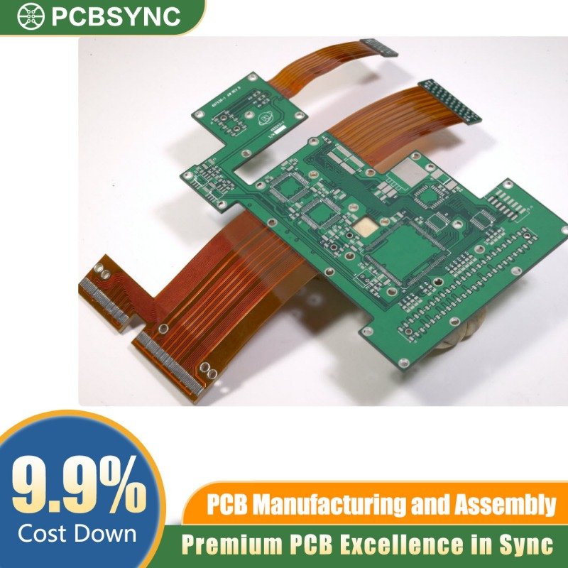
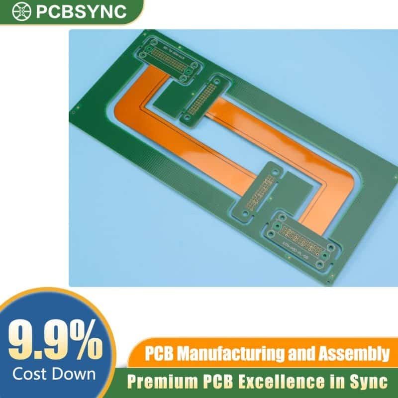
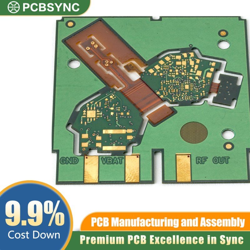
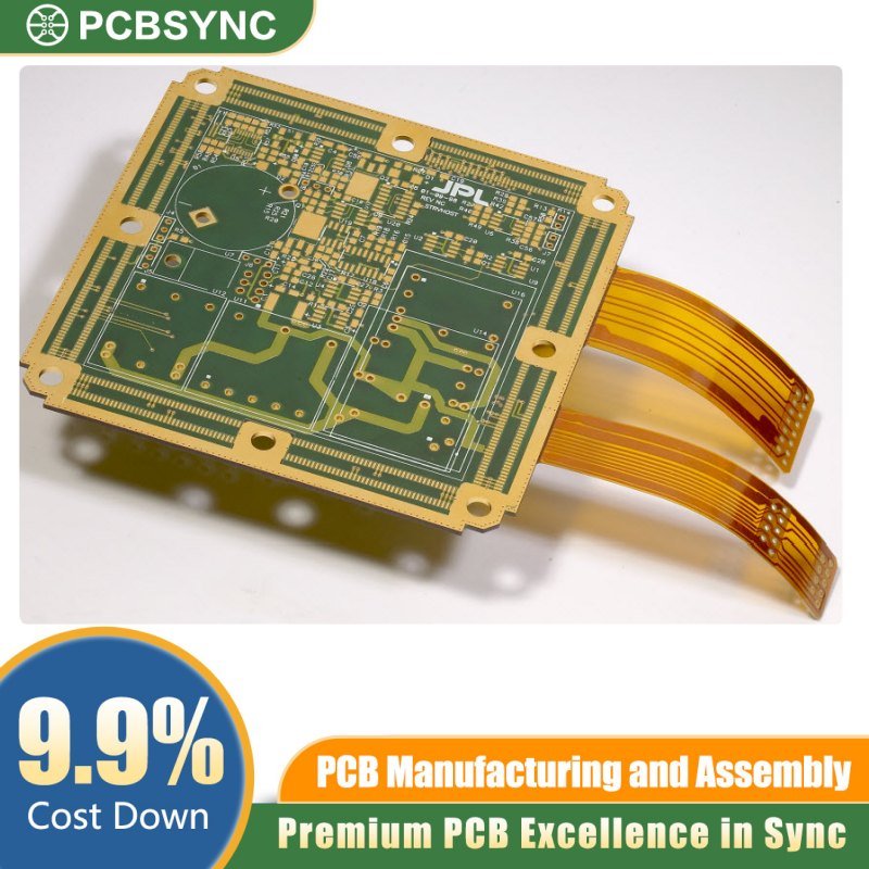
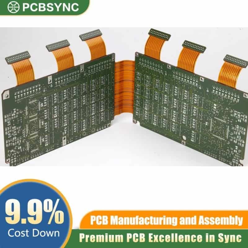
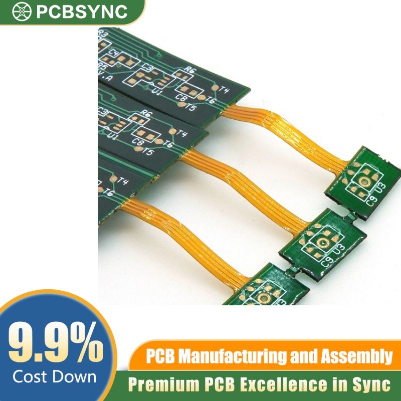
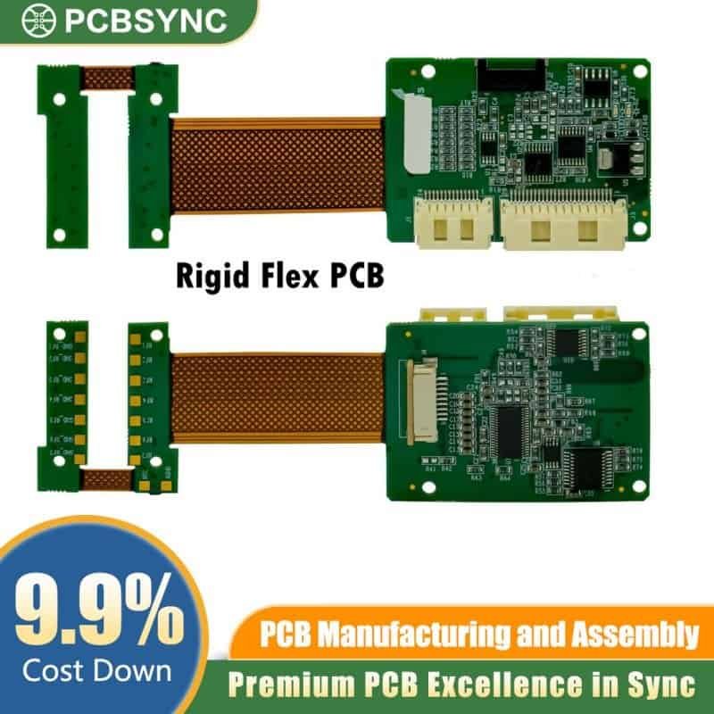
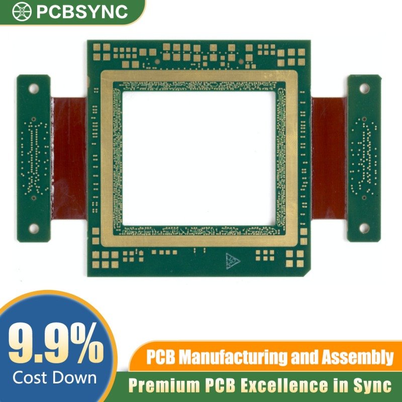
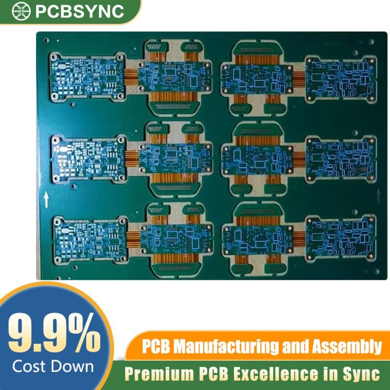
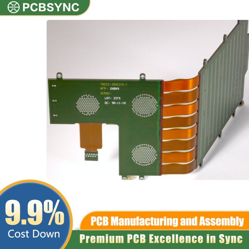
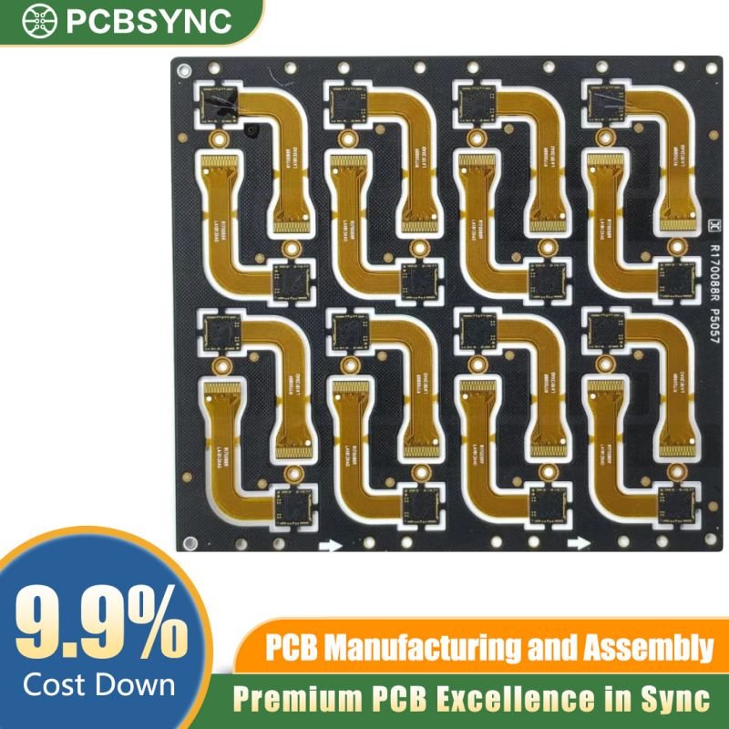
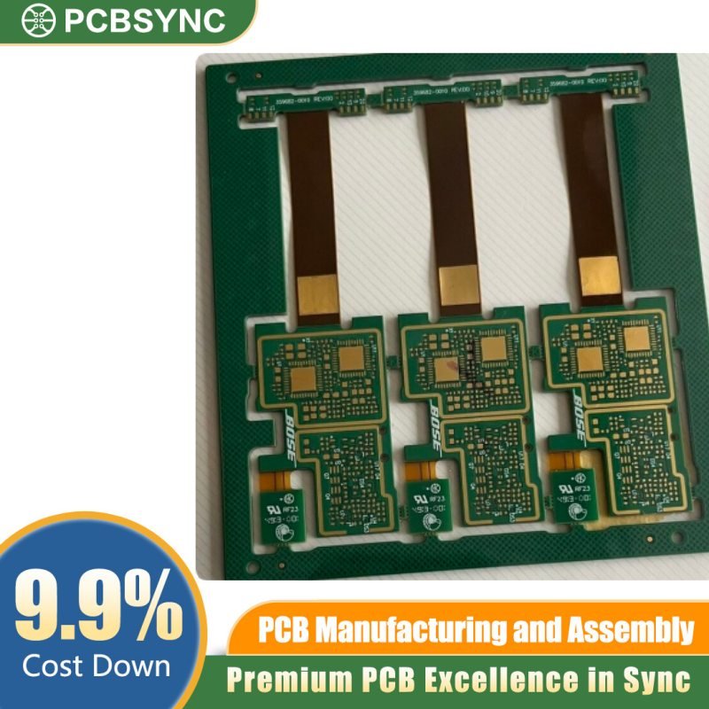
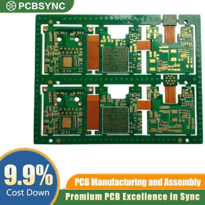
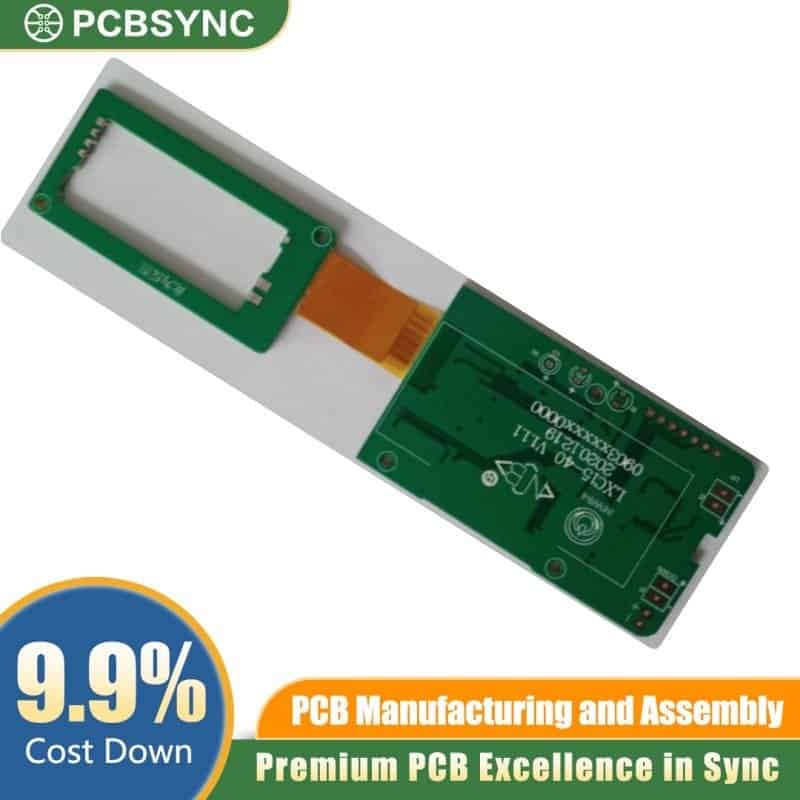
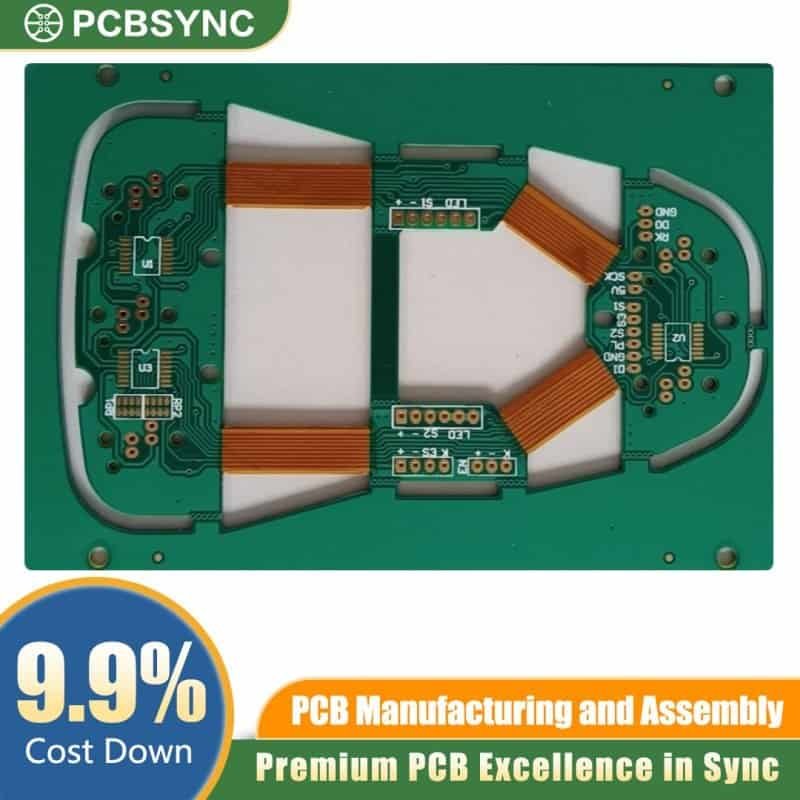
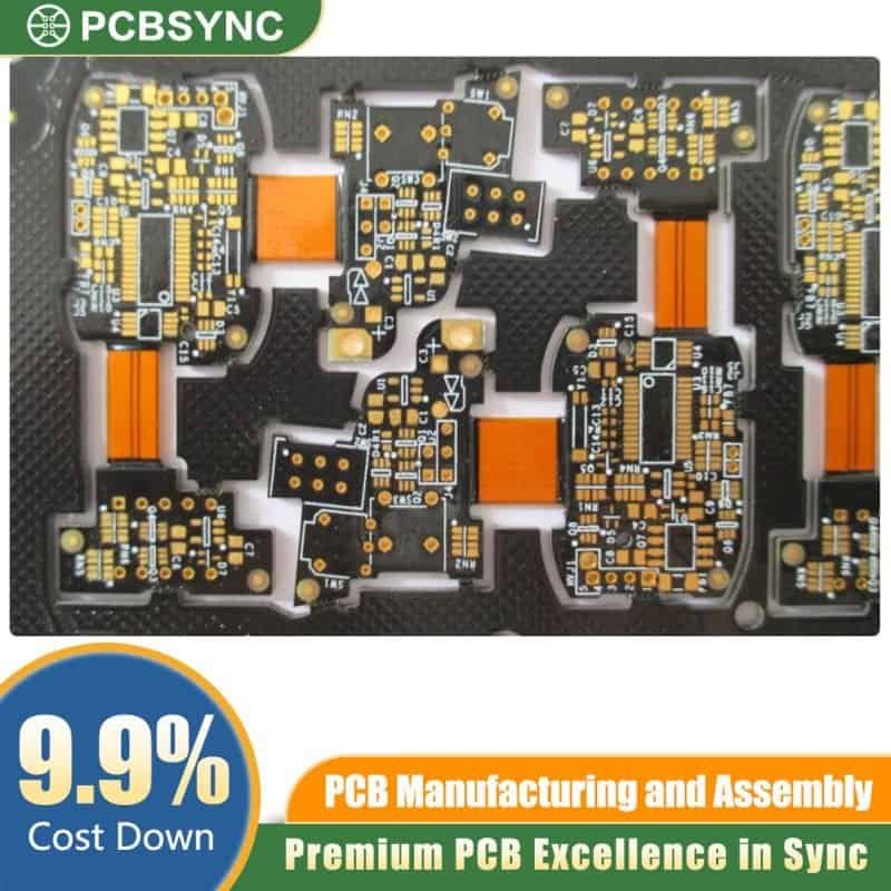
A rigid flex PCB combines rigid circuit boards with flexible circuit sections in a single integrated assembly. Unlike traditional PCBs that are entirely rigid or completely flexible, rigid flex boards feature strategic areas of both materials—rigid sections provide mechanical support and component mounting surfaces, while flexible sections enable bending, folding, and dynamic movement.
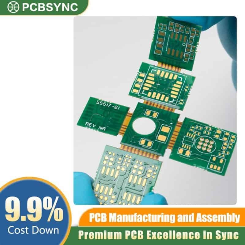
The construction typically involves layers of flexible polyimide material integrated with rigid FR-4 sections through a lamination process. The flexible portions run continuously through the rigid sections without physical connectors, creating a seamless electrical and mechanical connection.
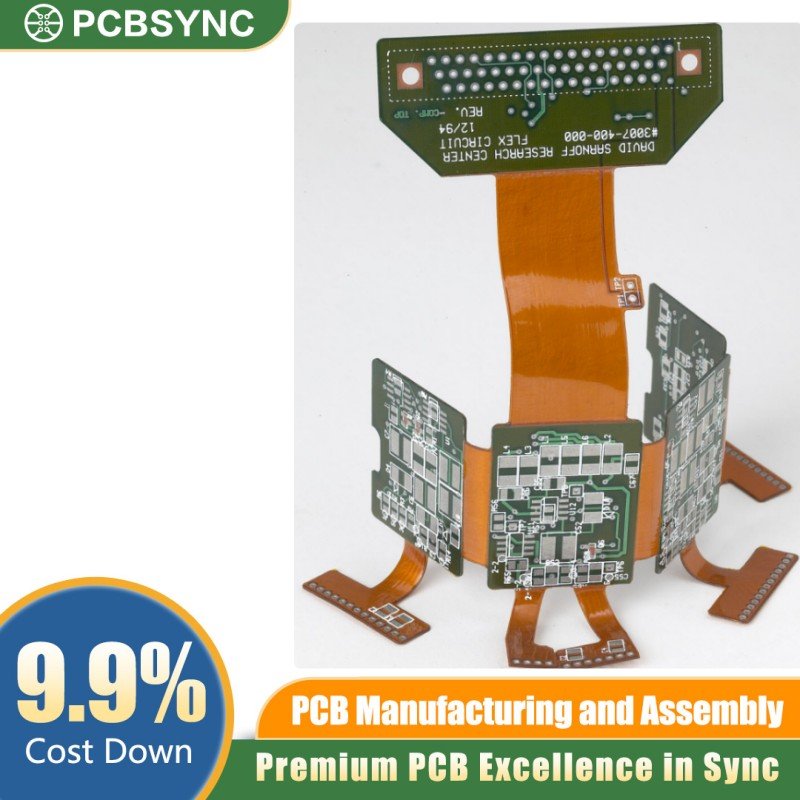
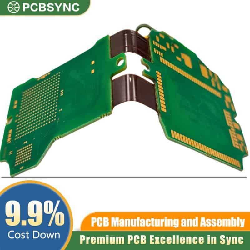
Think of it like the spine of a book—the rigid covers (rigid sections) provide structure and protection, while the flexible pages (flex sections) allow the book to open, close, and bend. Rigid flex PCBs work on the same principle, but instead of pages, you’re routing electrical signals through flexible polyimide that can bend repeatedly without failure.
How It Differs from Traditional PCBs
The fundamental difference lies in dimensionality. Traditional rigid PCBs force you to design in essentially two dimensions—you can stack layers vertically, but the board itself must remain flat. Flexible PCBs give you bendability but sacrifice the structural support needed for many components.
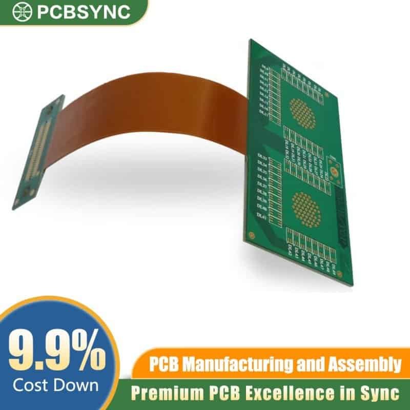
Rigid flex PCBs break these limitations. You can route traces around corners, fold sections back on themselves, and create truly three-dimensional assemblies. The rigid sections host your components, connectors, and any circuitry that needs a stable platform. The flex sections handle the connections between rigid areas, eliminating bulky cables and unreliable connectors.
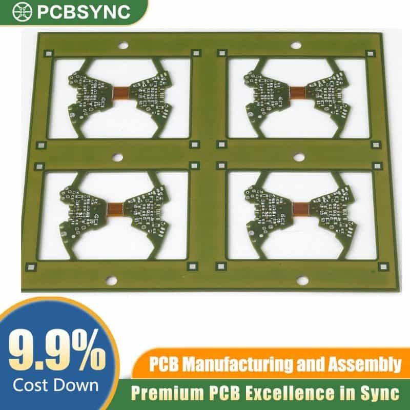
More importantly, the integration happens at the manufacturing level. Instead of building separate rigid boards and connecting them with flex cables (which introduces multiple potential failure points), everything is fabricated as one unit. This integration improves reliability, reduces assembly time, and often results in better signal integrity.
Construction and Materials: What Makes Rigid Flex Tick
Understanding the materials gives you insight into both capabilities and limitations of rigid flex technology.
Flexible Section Materials
The flexible portions use polyimide (PI) film as the base substrate. Polyimide offers excellent thermal stability (withstanding temperatures up to 260°C), chemical resistance, and mechanical properties that allow repeated flexing without degradation. The most common brand name you’ll encounter is Kapton, though several manufacturers produce equivalent materials.
For conductors, rolled annealed copper is preferred over electrodeposited copper in flex sections. Rolled annealed copper has a grain structure that makes it more ductile and resistant to fatigue from repeated bending. Thickness typically ranges from 0.5 oz to 2 oz copper, with thinner copper providing more flexibility.
The flexible layers are protected by coverlay (a flexible protective layer) or flexible solder mask. Coverlay is essentially a layer of polyimide with adhesive, die-cut to expose pads and vias while protecting the rest of the circuitry. This differs from rigid boards, which use liquid solder mask.
Rigid Section Materials
The rigid portions typically use standard FR-4 material—the same fiberglass-reinforced epoxy laminate found in conventional PCBs. This provides the mechanical strength needed to support components, connectors, and any mounting hardware.
In high-performance applications, you might encounter polyimide-glass rigid sections instead of FR-4. These offer better thermal performance and lower moisture absorption but come at a higher cost.
The Critical Bonding Process
The magic happens in the bonding between rigid and flexible sections. This requires specialized “no-flow” prepreg materials. Standard prepreg used in rigid board lamination would flow into the flexible areas during the heat and pressure of lamination, essentially turning your flexible sections rigid—defeating the entire purpose.
No-flow prepreg has a higher degree of pre-cure, preventing resin migration into flex areas while still bonding the layers together. Getting this right is crucial, which is why early collaboration with your PCB manufacturer is essential for rigid flex designs.
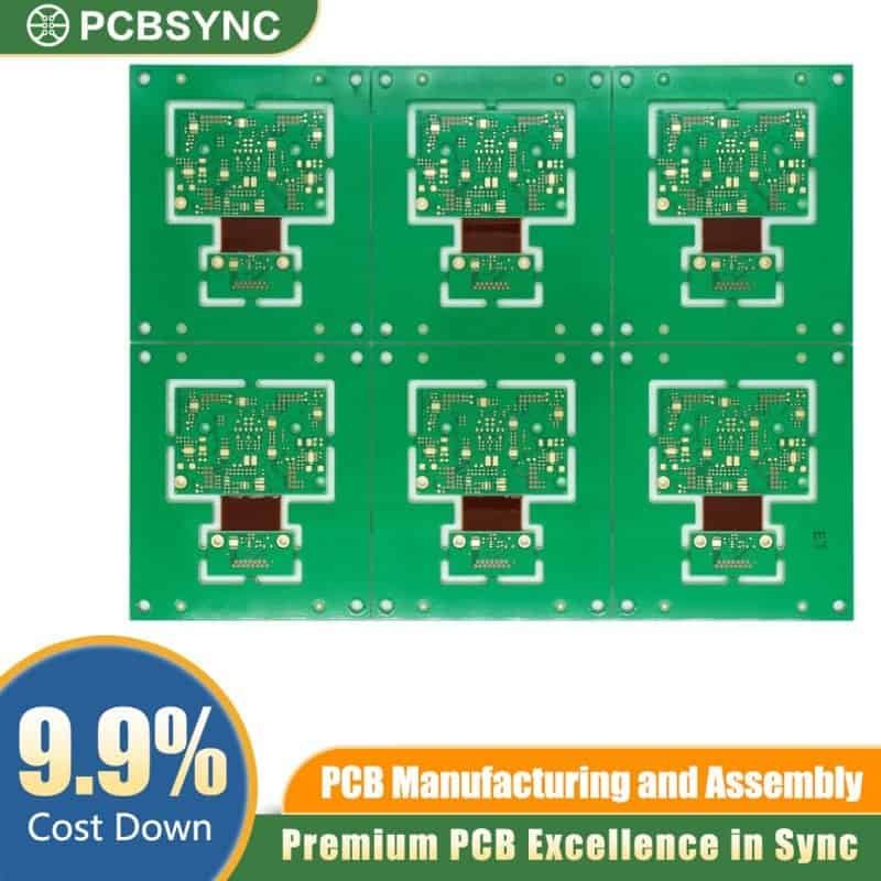
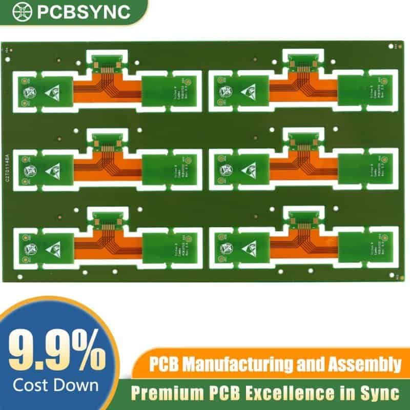
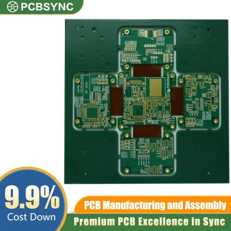
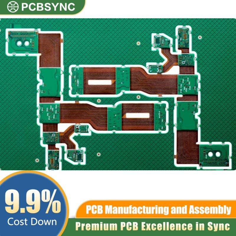
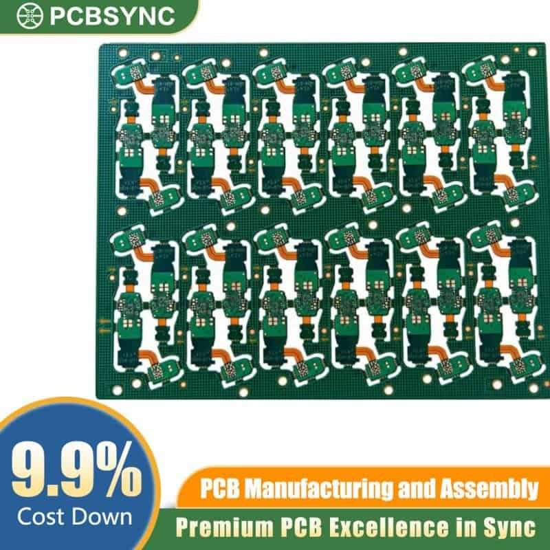
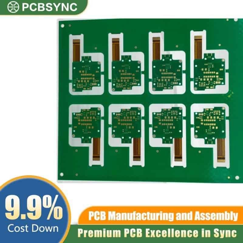
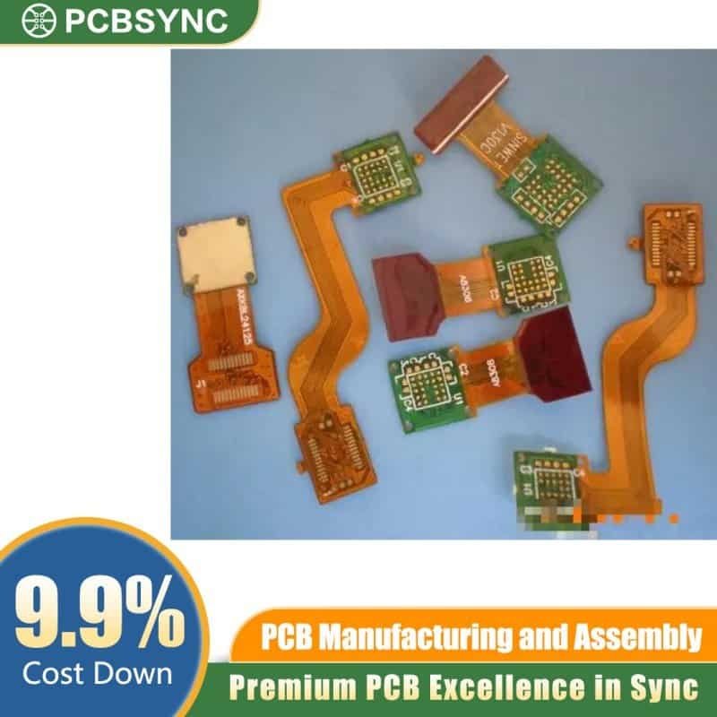
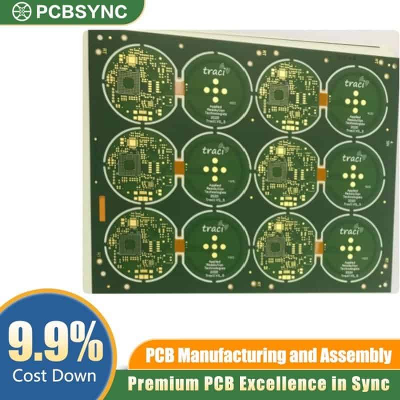
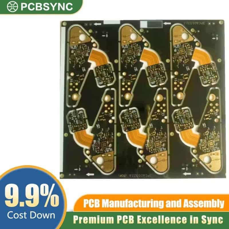
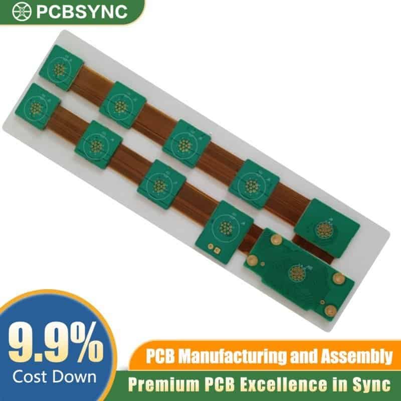
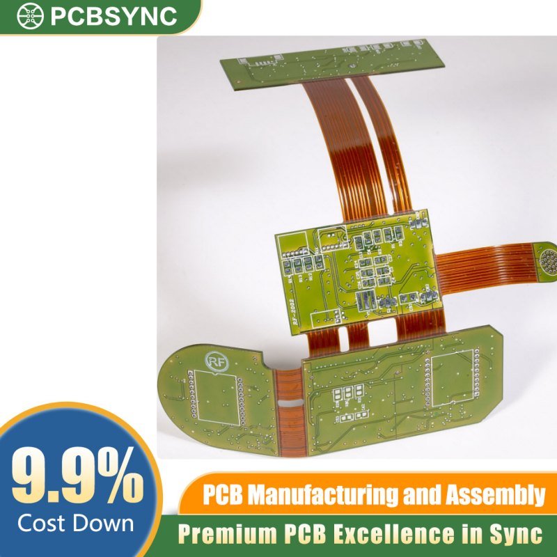
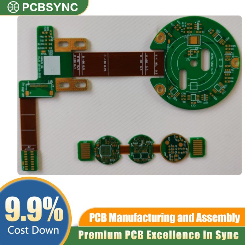
PCBSync Rigid Flex PCB Solution
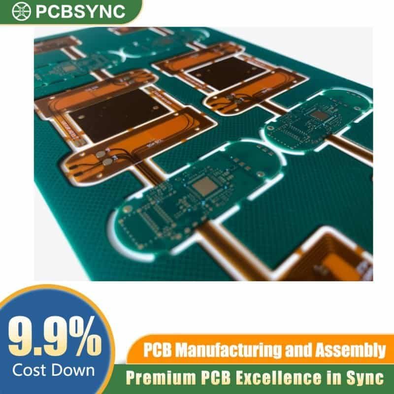
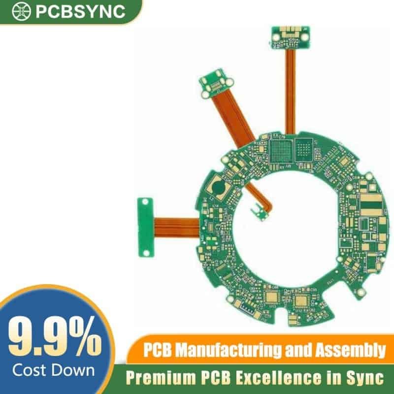
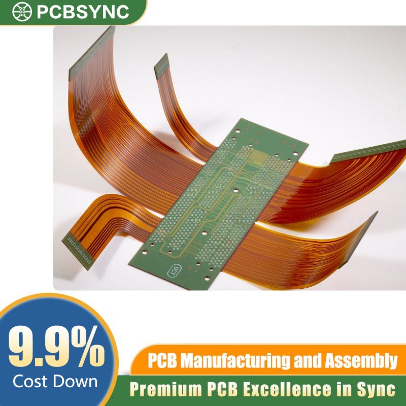
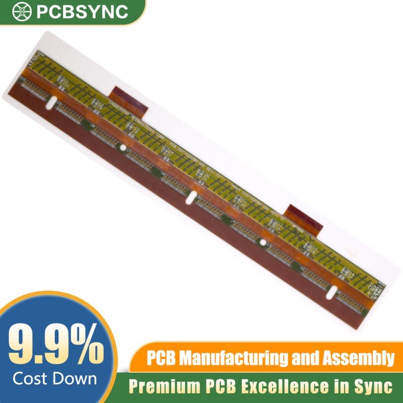
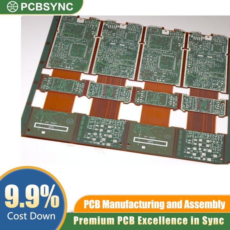
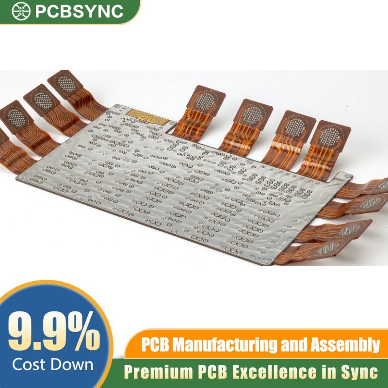
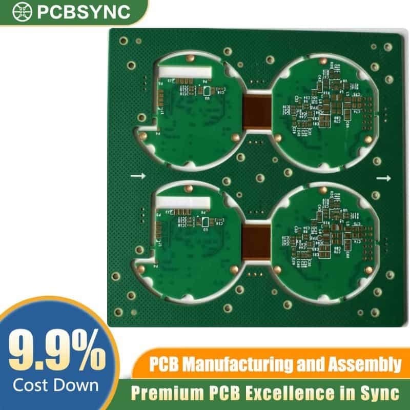
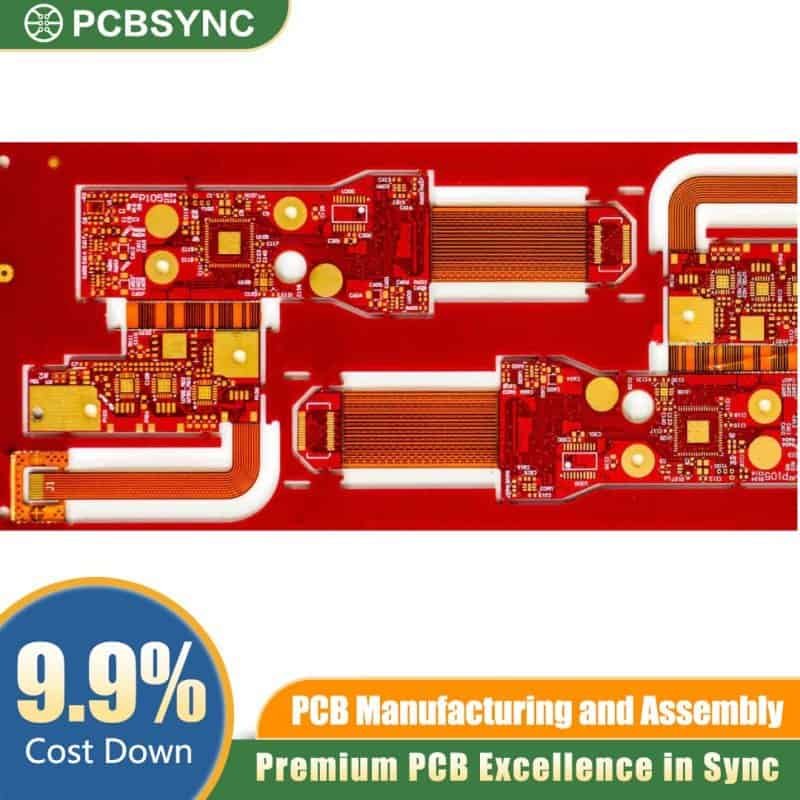
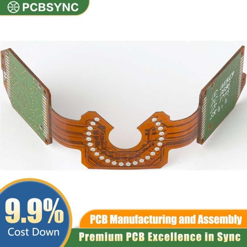
Rigid-flex PCBs have become a go-to solution across a broad range of industries, valued for their ability to combine structural stability with adaptability. Their durability and design flexibility make them well-suited for demanding applications — from wearables and medical devices to aerospace systems, automotive electronics, consumer tech, industrial automation, and telecommunications infrastructure. View more …
Rigid flex PCBs cost more than rigid boards—sometimes two to three times as much. So why use them? The benefits go beyond just “it bends.”
Space and Weight Savings That Actually Matter
When you eliminate connectors and cables between rigid sections, the space savings are significant. A typical board-to-board connector might add 5-10mm of height. Multiply that across multiple connections in a compact device, and suddenly you’re looking at substantial volume reduction.
Weight reduction is equally important. A rigid flex assembly replacing multiple rigid boards with cables can reduce total weight by 60% or more. For aerospace applications or wearables where every gram counts, this makes a tangible difference.
The ability to fold the assembly into three-dimensional shapes means you can fit electronics into spaces that would be impossible with rigid boards. That curved interior space in your device? Rigid flex can conform to it instead of leaving it empty.
Reliability Improvements You Can Measure
Every connector is a potential failure point. The contacts can corrode, loosen from vibration, or simply suffer from manufacturing variability. By eliminating these connections, rigid flex designs dramatically reduce failure modes.
Studies show that rigid flex assemblies can withstand vibration levels 10-20 times higher than equivalent rigid board assemblies with cable connections. This isn’t marketing fluff—it’s the difference between a system that works in harsh environments and one that fails in the field.
Solder joints on flex circuits experience less stress during thermal cycling because the flexible substrate can absorb some of the differential expansion. This extends the operational life in applications with wide temperature variations.
Assembly Cost Reduction (Yes, Really)
The upfront board cost is higher, but the total assembly cost can be lower. Instead of building multiple boards, sourcing connectors and cables, and manually assembling everything, you’re placing components on one integrated assembly.
This reduces:
Component count and associated inventory costs
Assembly steps and labor time
Testing complexity (test once instead of testing subassemblies)
Quality escapes from incorrect cable routing or connector mating
For products built in volume, these assembly savings can more than offset the higher board cost. The breakeven point typically occurs when you’re connecting four or more rigid sections, or when reliability requirements would force expensive connector solutions anyway.
Signal Integrity Benefits for High-Speed Designs
Shorter signal paths mean better signal integrity. Connectors and cables introduce impedance discontinuities that cause reflections and signal degradation. Direct copper traces on flex material maintain controlled impedance throughout the signal path.
This becomes critical for high-speed digital interfaces or RF applications. The continuous ground plane possible with rigid flex construction provides better EMI shielding than cables ever could.
Applications Where Rigid Flex Excels
Understanding where rigid flex technology provides genuine advantages helps you evaluate whether it’s right for your application.
Medical Devices: Where Failure Isn’t an Option
Medical applications pushed rigid flex development forward because the requirements are unforgiving—small size, high reliability, and often operation inside the human body.
Pacemakers use rigid flex assemblies to fit complex circuitry into the compact titanium housing while maintaining the flexibility needed during implantation. The rigid sections hold the battery connections, control circuitry, and antenna, while flex sections route signals to the electrode connections.
Hearing aids benefit from the three-dimensional design capability. The electronics can follow the curved shape of the ear canal, maximizing space utilization in a device that might be only 10mm in its largest dimension.
Surgical instruments like endoscopes need electronics that can navigate tortuous paths inside the body. Rigid flex assemblies can incorporate cameras, light sources, and control circuitry while maintaining the necessary flexibility for navigation.
Aerospace and Military: Proven in Extreme Conditions
When your electronics need to survive launch vibrations, operate in vacuum, and function across temperature ranges from -55°C to +125°C, material choices matter intensely.
Satellite systems use rigid flex assemblies extensively. The space and weight savings translate directly to reduced launch costs (at roughly $10,000 per kilogram to orbit, every gram saved is valuable). The high reliability means fewer mission failures from electronic malfunction.
Military avionics benefit from the vibration resistance. Aircraft experience constant vibration from engines and aerodynamic forces. Traditional assemblies with cables and connectors would fatigue and fail; rigid flex assemblies continue functioning.
Unmanned aerial vehicles (UAVs) combine all these requirements—weight reduction for flight performance, vibration resistance, and compact packaging in a small airframe. Rigid flex enables camera gimbals that can articulate while maintaining signal integrity for high-resolution video.
Consumer Electronics: Enabling Tomorrow’s Devices
Smartphones have been using rigid flex technology for years. That complex assembly that somehow fits a main processor board, battery management, camera modules, and display connections in a device thinner than a pencil? Rigid flex makes it possible.
Laptops use rigid flex for the connection between the main board and the display assembly. The rigid sections mount in the base and lid, while the flex section routes through the hinge area, flexing thousands of times over the laptop’s life.
Wearable devices depend on rigid flex to conform to body contours. Smartwatches need to pack an impressive amount of technology into a curved form factor worn on the wrist. Rigid sections hold the main processor, sensors, and battery connections, while flex sections follow the curved case design.
Foldable phones represent the cutting edge of rigid flex application. The display circuitry must flex repeatedly without failure, while also packing the density needed for modern smartphone functionality. This pushes flex technology to its limits.
Industrial and Automotive: Reliability Under Stress
Industrial robots need electronics in moving joints that can flex millions of times without failure. Rigid flex assemblies in robotic arms allow the electronics to move with the joint while maintaining reliable connections.
Automotive applications have exploded with advanced driver assistance systems (ADAS). Camera modules need to be small, lightweight, and able to withstand the vibration and temperature extremes of automotive environments. Rigid flex assemblies enable compact camera modules with reliable connections.
Electric vehicles use rigid flex for battery management systems. The need to route sensors throughout a large battery pack while maintaining reliability in a high-vibration environment makes rigid flex an attractive solution.
Design Considerations: Getting It Right
Designing rigid flex boards requires attention to details that don’t matter for rigid boards. Miss these, and you’ll discover the hard way that flex circuits can and will fail.
Bend Radius: The Make-or-Break Factor
The minimum bend radius determines how tightly you can fold the flex sections. Push past the minimum, and you’ll crack the copper traces or delaminate the layers. Neither is recoverable.
The basic rule: bend radius should be at least 6 times the total thickness for static applications (bent once during assembly and left in that position). For dynamic applications where the flex section bends repeatedly during normal operation, increase this to 10 times the thickness or more.
A two-layer flex section might be 0.2mm thick, meaning a minimum static bend radius of 1.2mm. That sounds small, but it adds up quickly when you’re routing multiple signals through tight spaces.
Layer count dramatically affects achievable bend radius. Each additional layer of copper and polyimide increases the stress during bending. More than three layers in a flex section that needs to bend tightly usually indicates you need to rethink your approach.
Trace Routing in Flex Areas: Following the Rules
Traces crossing bend lines must run perpendicular to the bend axis. This is counterintuitive if you’re used to rigid boards where routing direction doesn’t matter much. But in flex areas, parallel traces along the bend line experience differential stress during bending, leading to fatigue and eventual failure.
Trace width in flex areas typically needs to be wider than equivalent rigid sections. This isn’t about current capacity—it’s about mechanical stress. Wider traces distribute stress better and are more resistant to flex fatigue. A trace that might be 0.15mm on a rigid section should probably be 0.2mm or wider in a flex section that experiences dynamic flexing.
Hatched or crosshatched planes in flex areas improve flexibility compared to solid copper pours. The gaps in the pattern allow the material to flex more easily while still providing some shielding or power distribution capability.
Avoid placing vias in bend areas entirely if possible. The plated through-hole is a stress concentration point during bending. If you absolutely must have vias in a flex section, keep them at least 1mm from the actual bend line and use larger finished hole sizes to reduce stress.
Stiffeners: Adding Support Where Needed
Stiffeners are rigid materials (often FR-4) bonded to flex sections to provide localized rigidity. You need them in areas where components or connectors mount on the flex section—the flexible substrate alone can’t support the mechanical forces during assembly or use.
ZIF (Zero Insertion Force) connectors require specific thickness tolerances that flex material alone can’t meet. A stiffener brings the total thickness to the required specification.
Component areas need stiffeners to prevent damage during reflow soldering. The thermal expansion and weight of components can warp unsupported flex material, leading to solder joint defects or component damage.
Keep stiffeners at least 2mm from the bend line. If the stiffener extends too close to the bend, it defeats the purpose of the flex section and can create stress concentration at the stiffener edge during bending.
Transition Zones: Where Rigid Meets Flex
The transition between rigid and flex sections requires careful design. This is where the stress during bending is highest, and where most failures occur if not designed properly.
Maintain a keep-out zone around transitions—typically 1-2mm where you shouldn’t place vias, components, or minimum-width traces. This gives manufacturing tolerance and reduces stress concentration.
The rigid-to-flex transition should be gradual if possible. Some designs use a stepped approach where the flex material extends partially into the rigid section before the full rigid stackup begins. This distributes stress over a larger area.
Material Selection and Stackup Strategy
Symmetrical stackups are crucial for dimensional stability. The flex section should have balanced construction with copper layers positioned symmetrically. An unbalanced stackup will curl or twist, making assembly difficult and potentially causing reliability issues.
No-flow prepreg is mandatory where rigid and flex sections meet. Standard prepreg will flow into flex areas during lamination, making them rigid and defeating the entire design. Not all laminate suppliers offer no-flow options, so verify material availability with your fabricator early in the design process.
Adhesiveless construction offers better flexibility and thermal stability than adhesive-based materials. The tradeoff is higher cost and more limited supplier options. For high-reliability or dynamic flex applications, the improved performance often justifies the cost.
Rigid Flex vs Rigid vs Flexible PCB: Making the Right Choice
Understanding when rigid flex is actually the best solution requires comparing it honestly with alternatives.
When Rigid PCBs Make More Sense
If your design fits in a single plane and doesn’t need to bend, rigid PCBs are almost always more cost-effective. The simpler manufacturing process and mature supply chain mean lower costs and shorter lead times.
High layer count designs (12+ layers) are usually easier and cheaper to implement as rigid boards. While rigid flex can accommodate many layers, the complexity and cost increase rapidly beyond 8-10 layers.
Designs without significant space constraints often don’t benefit enough from rigid flex to justify the cost. If you have room for connectors and cables, the traditional approach might be perfectly adequate.
When Pure Flex Is Better
If your entire assembly needs to be flexible—think wearable sensors or flexible displays—pure flex circuits are the better choice. You don’t need the rigid sections, so why pay for them?
Flex circuits with stiffeners can replace rigid flex in many applications at lower cost. You lose the integrated construction, but gain manufacturing flexibility and cost advantages. This works well for static applications where the “bend-once-and-forget” approach is acceptable.
The Rigid Flex Sweet Spot
Rigid flex makes the most sense when:
You’re connecting 4+ rigid sections: The elimination of connectors and cables becomes economically justified
Reliability is critical: Medical, aerospace, or military applications where field failures are unacceptable
Dynamic flexing is required: The assembly must bend repeatedly during normal operation
3D packaging is essential: You need to route electronics through complex three-dimensional spaces
Weight and space are at a premium: Every cubic millimeter and gram matter to the application
The breakeven point depends on production volume, but typically rigid flex becomes attractive for volumes above 1,000 units annually when you’re replacing multiple rigid boards with cable assemblies.
Manufacturing Process: What Happens Behind the Scenes
Understanding the manufacturing process helps you design boards that are actually manufacturable and helps you communicate effectively with your fabricator.
Layer Construction and Lamination
Manufacturing starts by building the flex circuit layers separately. The flexible polyimide base gets copper cladded, then goes through standard photolithography to create the circuit pattern. Coverlay or flexible solder mask is applied for protection.
The rigid sections are built using standard rigid board processes—FR-4 core material, copper cladding, and circuit pattern creation.
The crucial step is lamination, where rigid and flex sections come together. This uses no-flow prepreg as discussed earlier, with precise control of temperature, pressure, and time. The no-flow prepreg must bond the layers without flowing into the flex areas.
Multiple lamination cycles may be required for complex designs. Each lamination cycle adds cost and potential for issues, so minimizing complexity helps control cost and improve yield.
Drilling and Plating
Drilling through the combined rigid-flex stackup is more challenging than drilling a uniform rigid board. The different materials drill differently—polyimide is soft and can tear, while FR-4 is hard and wears drill bits quickly. Special drill parameters and sometimes sequential drilling of different sections is required.
Plating the through-holes that span rigid and flex sections requires careful process control. The aspect ratio (hole depth to diameter ratio) affects plating uniformity, and the material differences between sections complicate the chemistry.
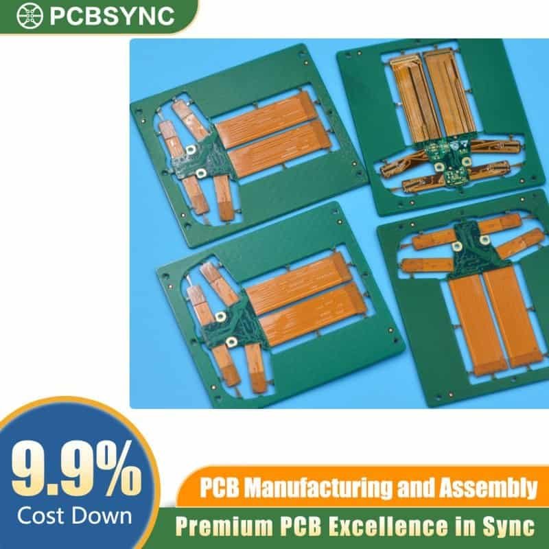
Outline Routing and Depaneling
Creating the board outline involves routing (mechanical milling) to define the board shape. For rigid flex, this includes cutting the grooves that define transitions between rigid and flex sections.
Deep milling creates the transition zones by removing rigid material over flex areas. The depth control must be precise—cut too deep and you damage the flex layers, cut too shallow and the flex section won’t bend properly.
Quality Control Challenges
Testing rigid flex boards requires specialized fixtures that can accommodate the non-planar nature of the final assembly. Electrical testing must verify all connections while the board is in a test-compatible configuration.
Visual inspection is more challenging because not all areas of the board are visible simultaneously when it’s in its final folded configuration. X-ray inspection may be needed to verify internal features.
Cost Factors and ROI Considerations
Let’s address the elephant in the room: rigid flex PCBs are expensive. But “expensive” needs context.
What Drives Rigid Flex Costs
Material costs are higher—polyimide costs more than FR-4, and no-flow prepreg is a specialized material with limited suppliers. The copper cladding process for flex materials requires more careful handling than rigid materials.
Manufacturing complexity adds cost at every step. More lamination cycles, specialized drilling parameters, careful outline routing, and complex testing all require additional time and have lower yields than equivalent rigid boards.
Layer count in the flex sections disproportionately affects cost. Each additional flex layer requires another lamination cycle and further complicates the stackup. A two-layer flex section is the most economical; four layers gets expensive fast.
The Total Cost Picture
But consider what you’re eliminating:
Multiple rigid boards (including setup costs for each)
Connectors (which can cost $5-20 each in low volumes)
Cable assemblies (material + assembly labor)
Assembly time to connect everything
Testing of subassemblies before final integration
Rework costs from incorrect cable routing or connector issues
For a product connecting six rigid boards with current total cost of $40 in boards plus $60 in connectors/cables/assembly, a single rigid flex board at $80 represents a significant savings while improving reliability.
Volume Economics
At very low volumes (under 100 units), the cost disadvantage of rigid flex is usually too large to overcome unless reliability absolutely demands it. The engineering cost to design rigid flex also needs to be amortized.
At moderate volumes (1,000-10,000 units), the assembly savings often make rigid flex economically attractive for complex assemblies.
At high volumes (100,000+ units), both the board cost and assembly cost advantages become significant. The reliability improvements also reduce warranty and field service costs.
Common Design Mistakes to Avoid
Learning from others’ mistakes is cheaper than making them yourself.
Ignoring the Transition Zones
Placing vias, components, or minimum-width traces right at the rigid-to-flex transition is a recipe for failure. These areas experience high stress, and anything that concentrates stress further will fail during manufacturing or use.
Always maintain the keep-out zones specified by your fabricator. If they say 1.5mm, don’t try to sneak in at 1.2mm because you’re tight on space. The specification exists because that’s where failures occur.
Inadequate Bend Radius
Designers sometimes calculate the minimum bend radius and then use exactly that value, leaving no margin. Manufacturing tolerances, material variations, and actual use conditions mean you need margin.
Add 20-30% to calculated minimum bend radius as a safety factor. If your calculation says 2mm minimum, design for 2.5mm. The slight increase in required space can prevent field failures.
Incorrect Layer Transitions Between Regions
Traces changing layers at or near the transition between rigid and flex sections cause problems. The via is already a stress point; placing it where material properties are changing makes failure much more likely.
Route traces to the layer they need to be on while still in the rigid section, well before the transition zone begins. This distributes stress and improves reliability.
Treating Flex Areas Like Rigid Board
Applying rigid board design rules to flex sections is tempting but wrong. Minimum trace widths, spacing rules, and via sizes that work fine on rigid boards may not be adequate for flex sections that experience mechanical stress.
Consult your fabricator’s flex-specific design rules. They’re usually more conservative than rigid board rules, and for good reason.
Future Trends in Rigid Flex Technology
The technology continues evolving, opening new applications.
Embedded Components
Embedding passive components (resistors, capacitors) within the rigid flex stackup saves space and can improve electrical performance. The components are placed in cavities within the laminate and connected to circuit layers directly.
This technology is still expensive and limited to specific component types, but adoption is growing in space-constrained high-reliability applications.
Higher Layer Counts
Manufacturing process improvements are pushing practical layer counts higher. Rigid flex assemblies with 20+ total layers (though typically fewer in the flex sections) are becoming more feasible.
This enables replacement of entire backplane assemblies with single rigid flex constructions in some applications.
Improved Materials
New polyimide formulations offer better thermal stability, lower dielectric loss for high-frequency applications, and improved laser drilling characteristics. These materials enable designs that weren’t possible with earlier materials.
Thermoplastic materials as potential replacements for thermoset materials could enable new manufacturing processes and improve recyclability.
Integration with Advanced Packaging
Combining rigid flex PCBs with advanced semiconductor packaging techniques like chip-on-flex allows even greater integration. The chip is mounted directly on the flex section, eliminating packaging and allowing the thinnest possible profile.
Frequently Asked Questions
How long do rigid flex PCBs last?
Properly designed rigid flex PCBs can last 20+ years in static applications where they’re bent once during assembly and then remain fixed. For dynamic flex applications with repeated bending, lifetime depends on the number of flex cycles and design factors like bend radius and copper thickness. Well-designed dynamic flex circuits can withstand millions of flex cycles. The key is following design guidelines for your specific application—static or dynamic flexing requires different approaches.
Can you repair a rigid flex PCB?
Repairing rigid flex PCBs is significantly more difficult than repairing rigid boards. The flexible substrate doesn’t handle heat well during rework, and the thin copper traces are easily damaged. Component replacement is possible but requires specialized equipment and skilled technicians. In practice, most rigid flex assemblies are considered non-repairable, which makes getting the design right the first time even more important.
What’s the minimum order quantity for rigid flex PCBs?
Most PCB fabricators will accept rigid flex orders as low as 5-10 pieces, though the per-unit cost at these volumes is extremely high due to setup costs. Prototyping typically makes sense at 5-25 pieces. For cost-effectiveness, plan on volumes of 100+ units for production. The exact minimums and pricing breaks vary significantly by fabricator and design complexity.
How much does a rigid flex PCB cost compared to rigid?
Rigid flex PCBs typically cost 2-4 times as much as comparable rigid boards, depending on complexity. A simple 2-layer rigid board might cost $5-10 in moderate volume, while an equivalent rigid flex board with 2-layer flex sections could cost $20-40. However, this comparison misses the point—you need to compare total assembly cost including connectors, cables, and assembly labor. The fully-assembled rigid flex solution often costs less than multiple rigid boards connected together.
What CAD software works best for rigid flex design?
Major PCB design tools including Altium Designer, Cadence OrCAD/Allegro, and Mentor (Siemens) Xpedition all support rigid flex design with specialized features for defining flex regions, bend lines, and stackup variations. Altium Designer is popular for its relatively intuitive interface and 3D visualization. For rigid flex specifically, the software needs to handle multiple stackup regions, flexible outline definitions, and preferably 3D folding visualization to verify the design works in its final folded state.
Conclusion: Is Rigid Flex Right for Your Project?
Rigid flex PCBs solve specific problems extremely well—primarily around fitting electronics into tight spaces while maintaining high reliability. But they’re not a universal solution.
Use rigid flex when you’re connecting multiple rigid sections and reliability matters more than initial cost. The technology excels in aerospace, medical, and military applications where field failures are unacceptable. It’s becoming increasingly viable for consumer products as manufacturing processes improve and volumes increase.
Skip rigid flex if your design fits comfortably in a single plane, if your budget can’t absorb the 2-4x higher board cost, or if your volume is too low to justify the engineering investment.
The key is making the decision based on total system cost and reliability requirements, not just the PCB price. When you factor in assembly costs, reliability improvements, and field service reduction, rigid flex often delivers better value than it first appears.
Work closely with your PCB fabricator from the start of your design. Their experience with rigid flex manufacturing can save you from costly mistakes and help you optimize the design for both performance and manufacturability. The upfront collaboration investment pays off in working prototypes and smooth production ramps.
Inquire: Call 0086-755-23203480, or reach out via the form below/your sales contact to discuss our design, manufacturing, and assembly capabilities.
Quote: Email your PCB files to Sales@pcbsync.com (Preferred for large files) or submit online. We will contact you promptly. Please ensure your email is correct.
Notes: For PCB fabrication, we require PCB design file in Gerber RS-274X format (most preferred), *.PCB/DDB (Protel, inform your program version) format or *.BRD (Eagle) format. For PCB assembly, we require PCB design file in above mentioned format, drilling file and BOM. Click to download BOM template To avoid file missing, please include all files into one folder and compress it into .zip or .rar format.


