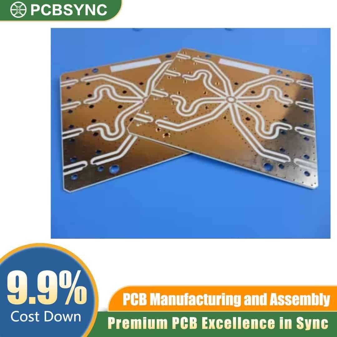
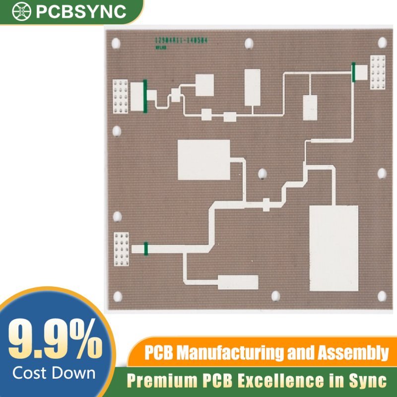
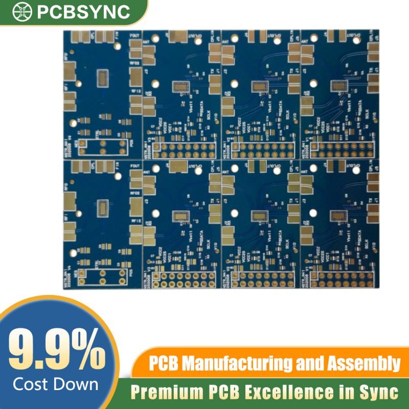
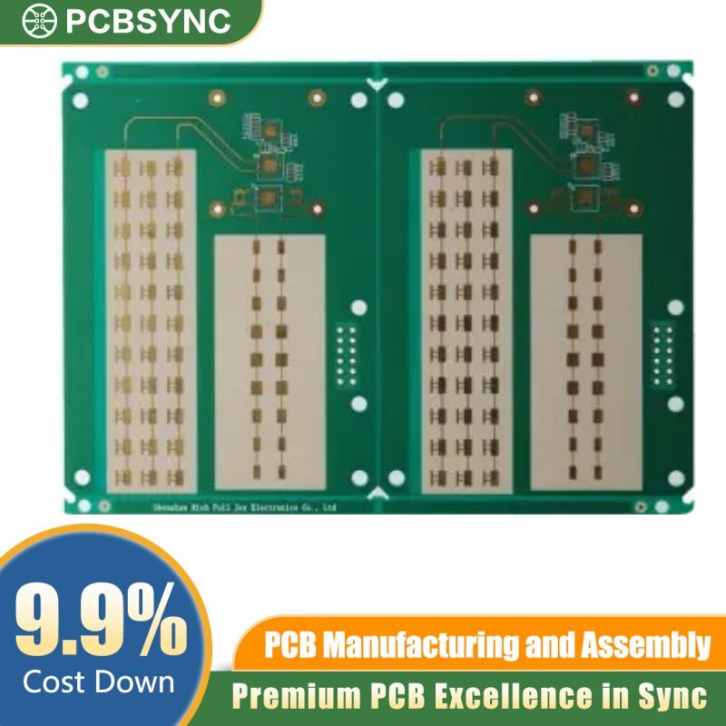
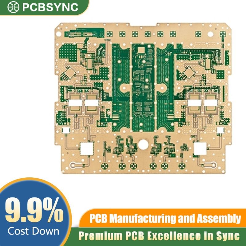
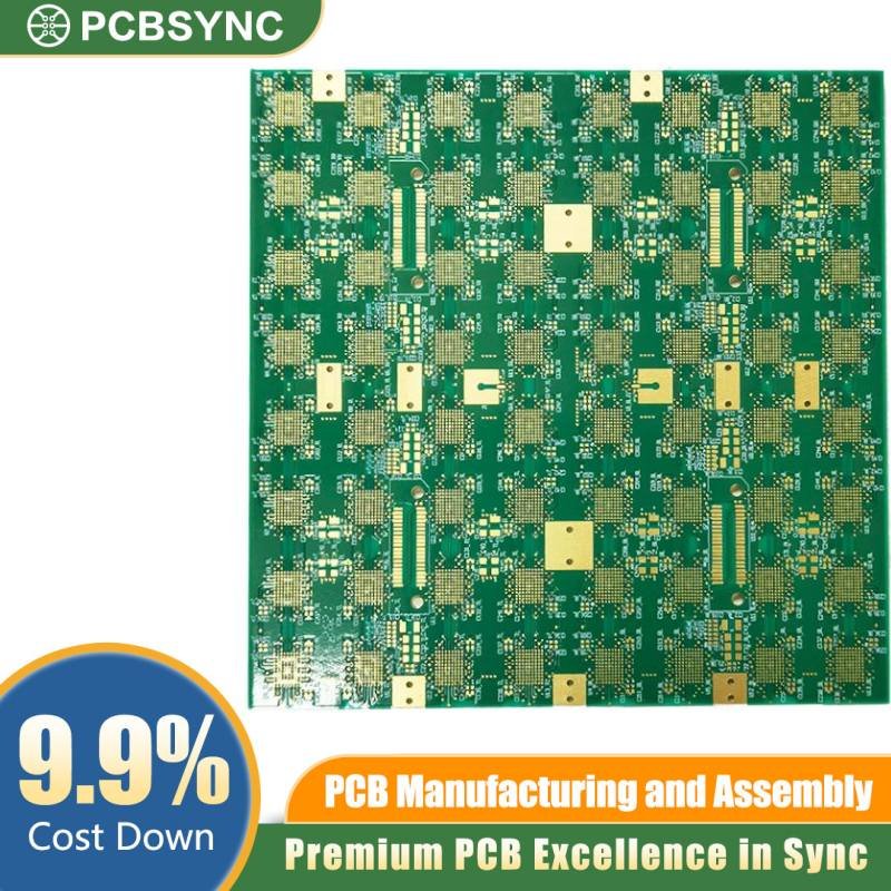
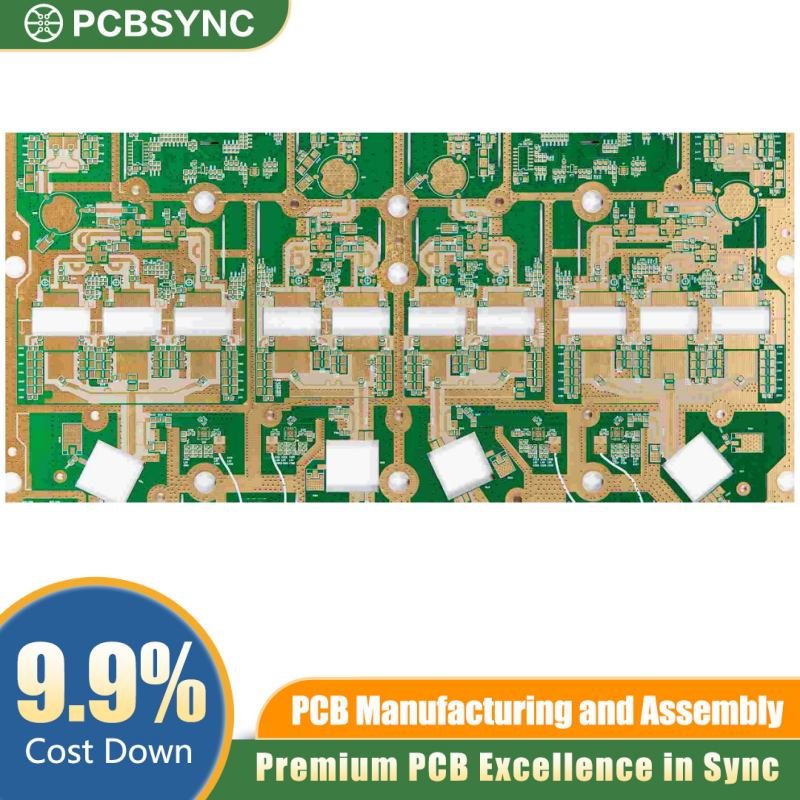
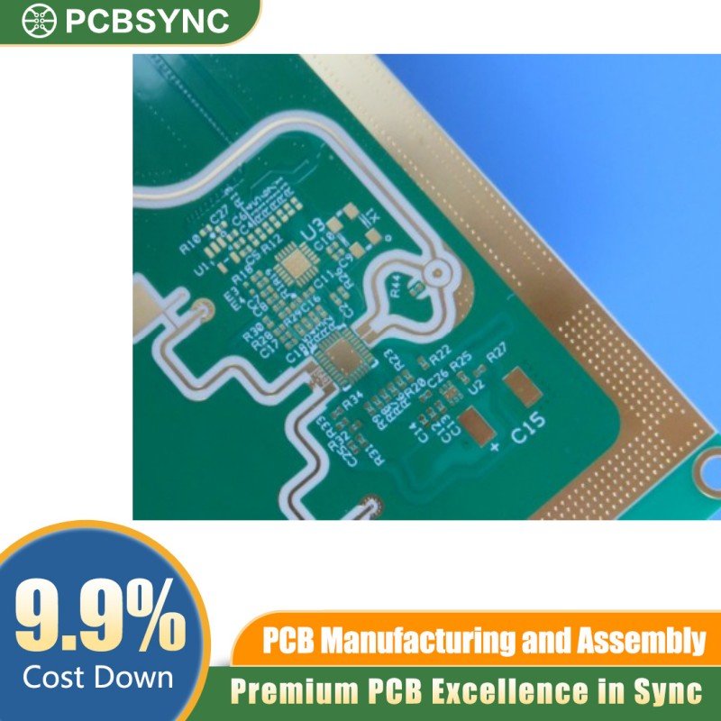
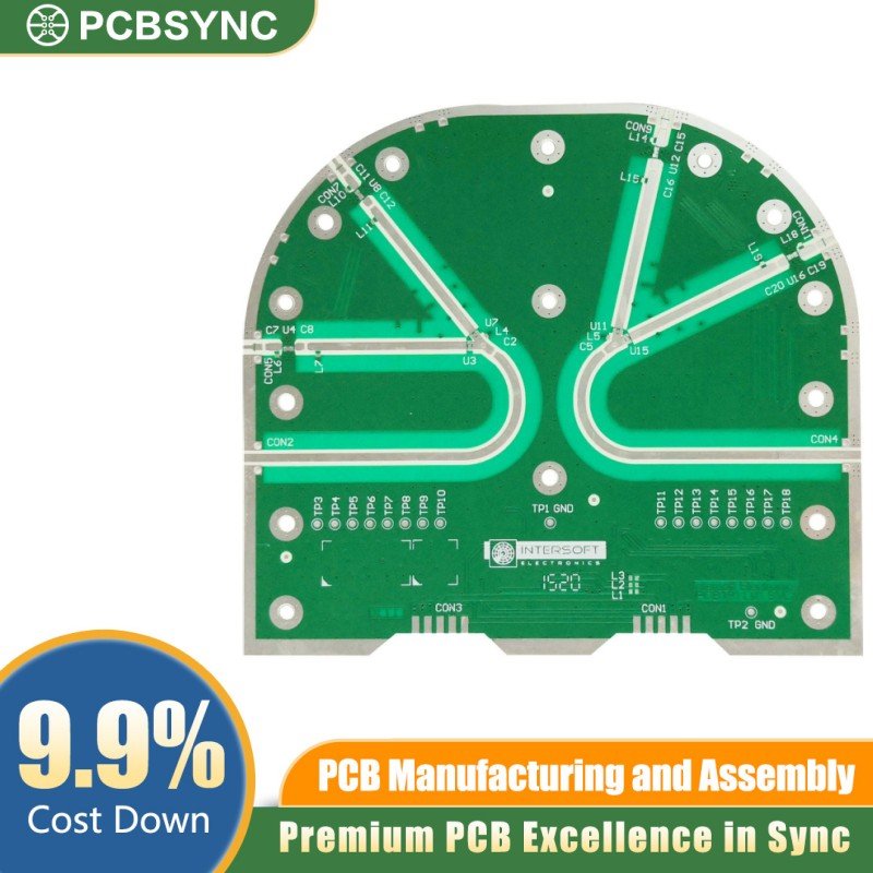
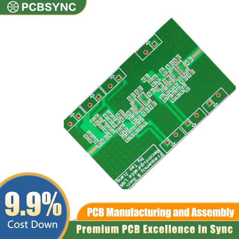
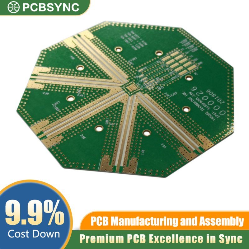
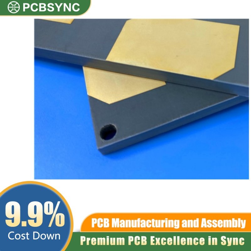
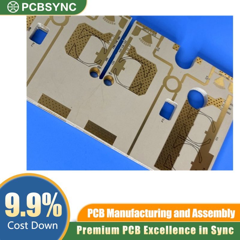
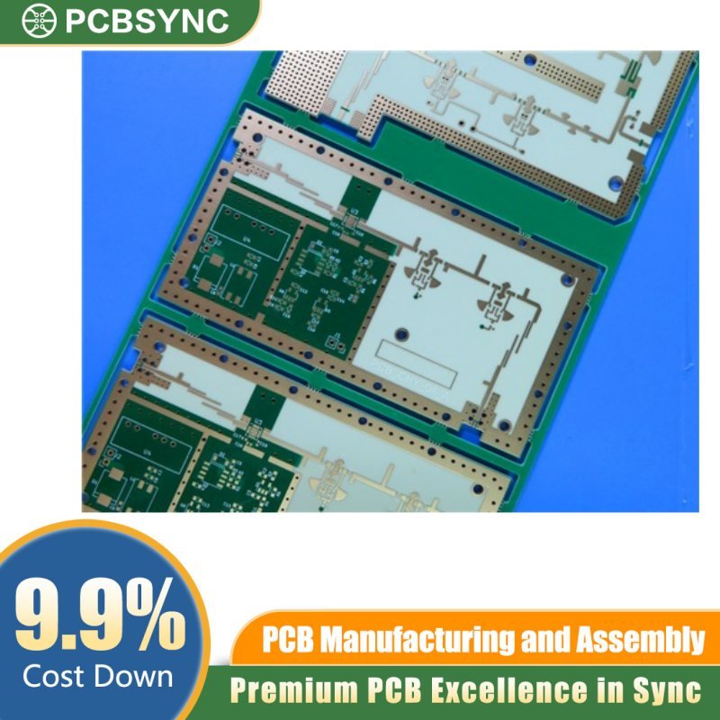
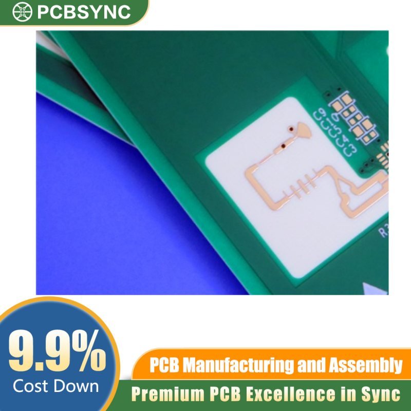
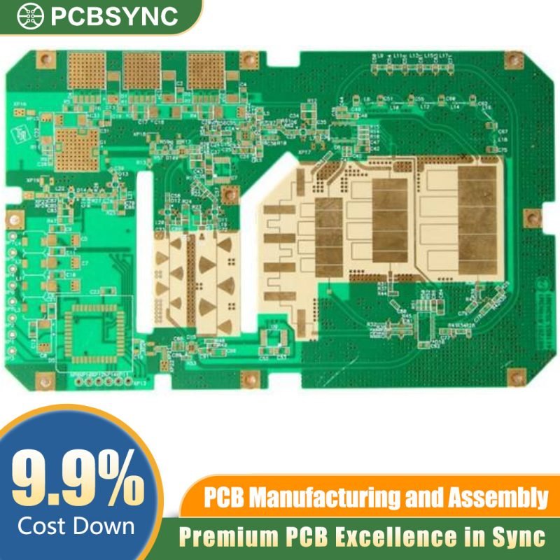
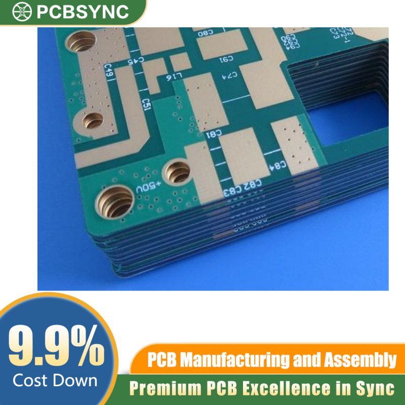
The RO4700 16-Layer Smart Grid Communication PCB is an elite-tier interconnect solution designed specifically for the rigorous demands of next-generation power distribution and industrial telecommunications. Engineering for the Smart Grid requires a delicate balance of thermal stability, signal integrity, and long-term environmental resilience. This PCB leverages the industry-leading Rogers RO4700™ Series dielectric to provide consistent electrical performance in mission-critical infrastructure.
Key Technical Specifications
-
Base Material: Rogers RO4700™ (High-Frequency Laminate)
-
Layer Count: 16-Layer High-Density Interconnect (HDI)
-
Board Thickness: 2.4mm (Enhanced structural rigidity)
-
Copper Weight: 2oz Finished Copper (Superior current carrying capacity)
-
Surface Finish: Hard Gold (Electrolytic Gold over Nickel)
-
Application: Smart Grid Infrastructure, Base Stations, and Power Automation
Engineered for the Modern Smart Grid
In the era of decentralized energy and IoT-integrated power grids, communication hardware must process massive data throughput without latency or signal degradation. The RO4700 substrate is a low-loss, thermoset laminate that offers a low dielectric constant ($D_k$) and a low dissipation factor ($D_f$). This ensures that high-frequency signals remain crisp and interference-free, even in electrically “noisy” environments like substations and industrial hubs.
The 16-layer stackup provides ample routing real estate for complex differential pairs and dedicated power/ground planes. This multi-layer architecture is essential for electromagnetic interference (EMI) shielding, ensuring that your Smart Grid communication modules comply with strict international regulatory standards.
Why Choose Hard Gold Surface Finish?
Unlike standard ENIG, our Hard Gold (Electrolytic Gold) finish is designed for maximum durability. By incorporating a small percentage of cobalt or nickel into the gold layer, the surface becomes significantly more resistant to mechanical wear.
-
Wear Resistance: Ideal for edge connectors and sliding contacts that require repeated mating cycles.
-
Corrosion Protection: Provides a formidable barrier against oxidation in harsh, outdoor grid environments.
-
Superior Conductivity: Maintains low contact resistance over the entire lifespan of the device.
Thermal Management and 2oz Copper
Managing heat is the primary challenge in power grid electronics. This PCB features 2oz copper weight, doubling the standard thickness to allow for higher current loads and better heat dissipation. At a 2.4mm thickness, the board offers the mechanical strength needed to support heavy components and withstand the vibrations often found in industrial enclosures.
Why Source from PCBSync?
At PCBSync, we understand that Smart Grid reliability is non-negotiable. Our manufacturing process for the RO4700 series involves rigorous Automated Optical Inspection (AOI), Flying Probe Testing, and Impedance Control Verification to ensure every board meets your exact impedance targets (typically 50Ω or 100Ω differential).
Whether you are developing automated meter reading (AMR) systems, distribution automation controllers, or wide-area monitoring systems, the RO4700 16-Layer Smart Grid PCB is the backbone your technology deserves.
Order your RO4700 High-Frequency PCBs today from PCBSync and experience the pinnacle of signal integrity and industrial durability.