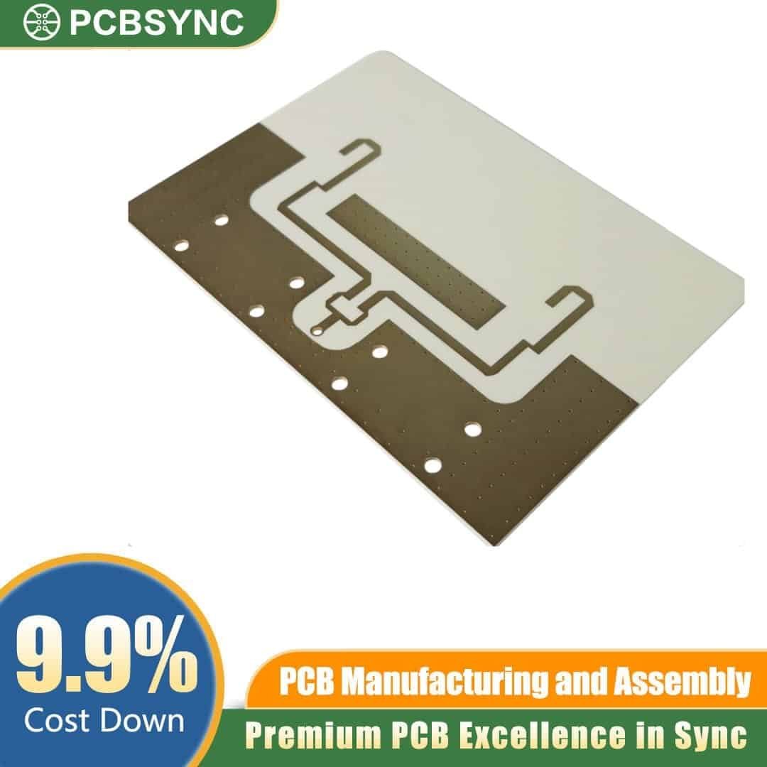
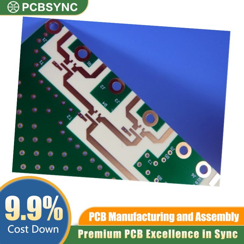
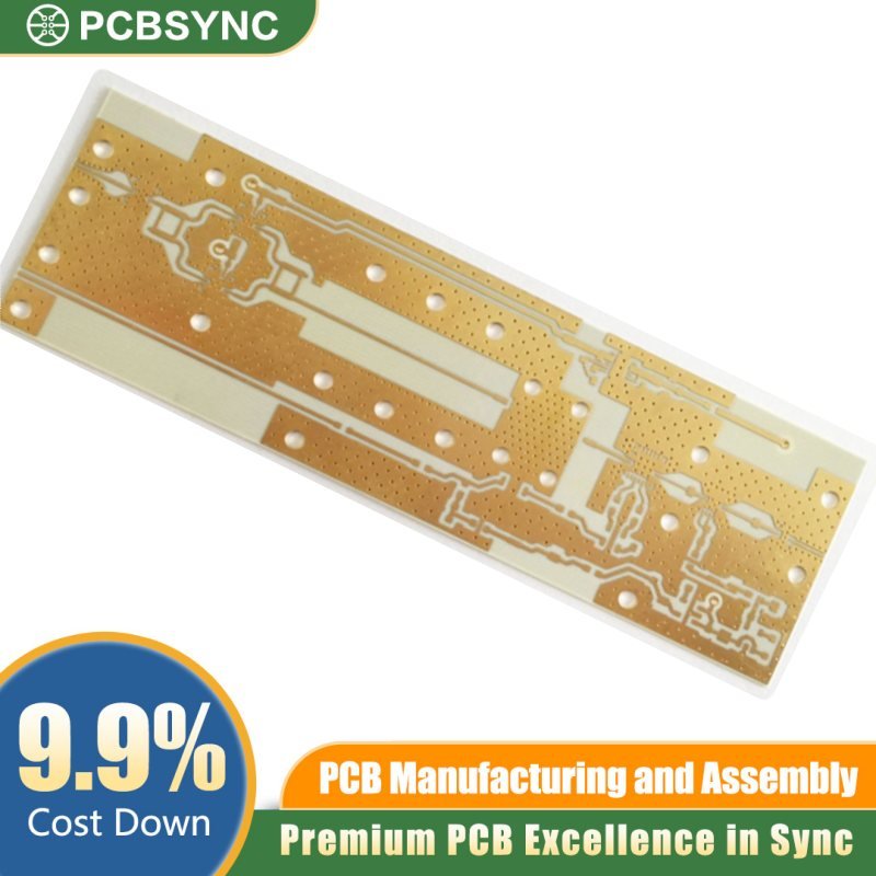
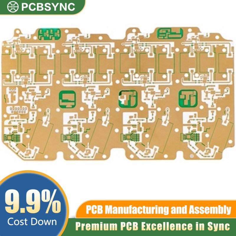
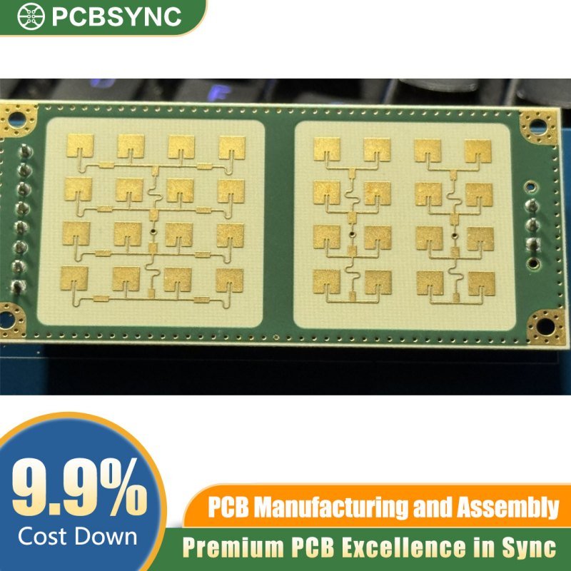
Precision-Engineered for Mission-Critical RF & Microwave Applications
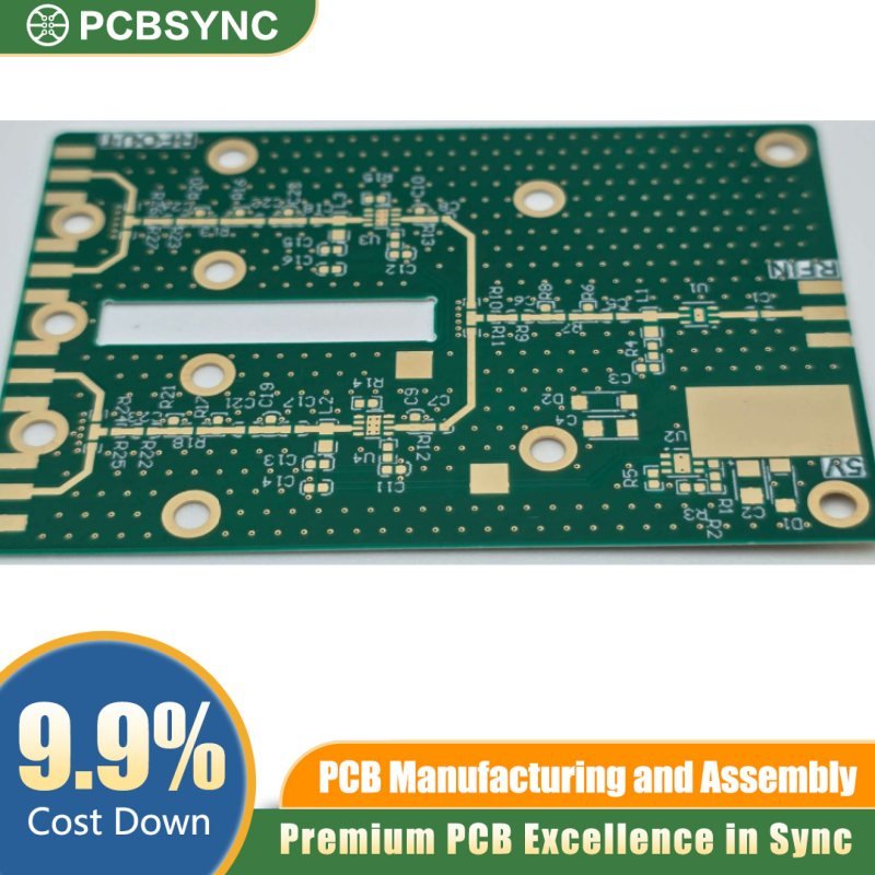
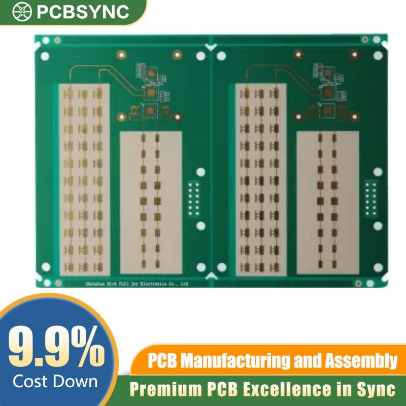
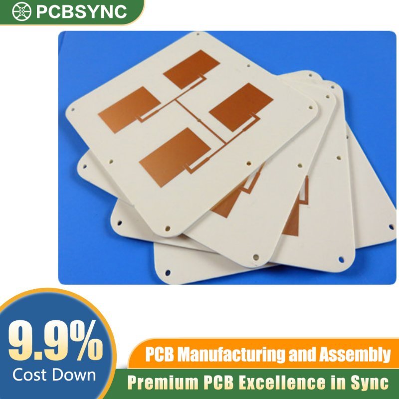
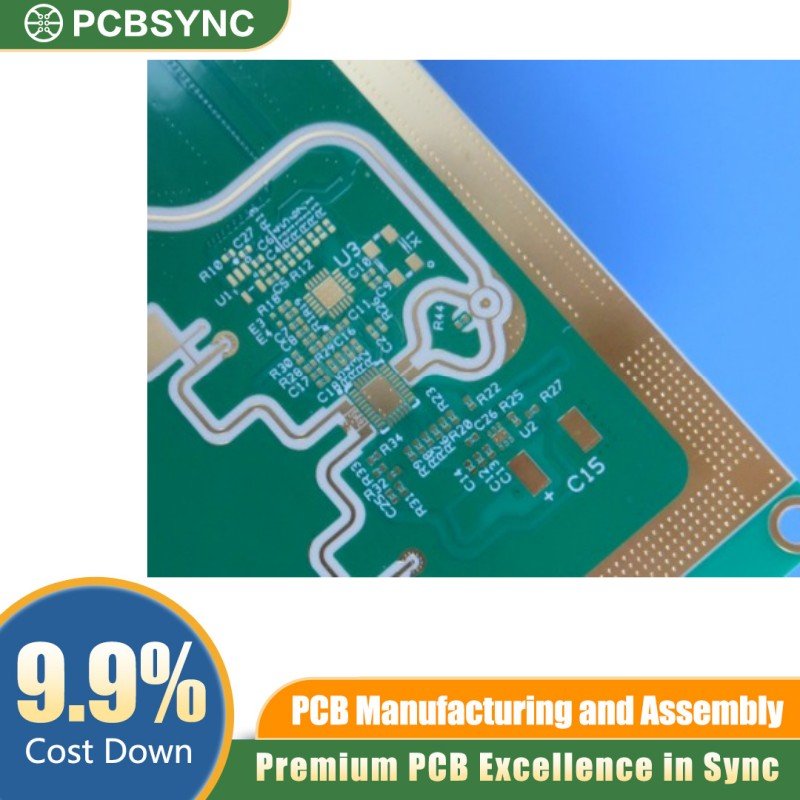
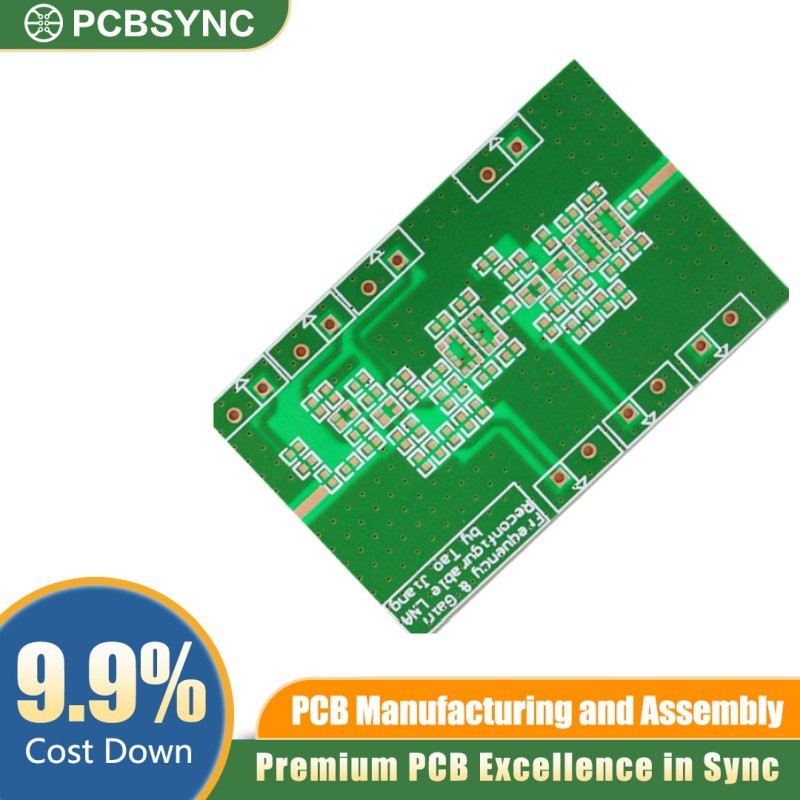
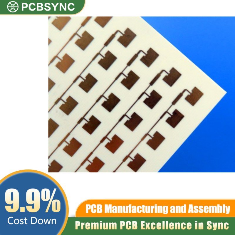
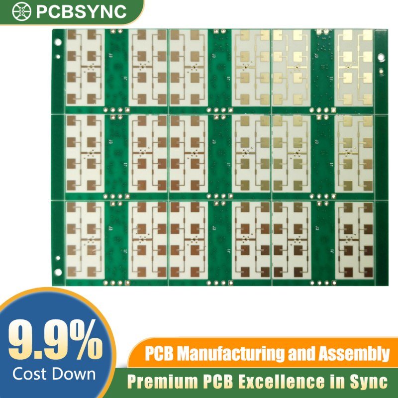
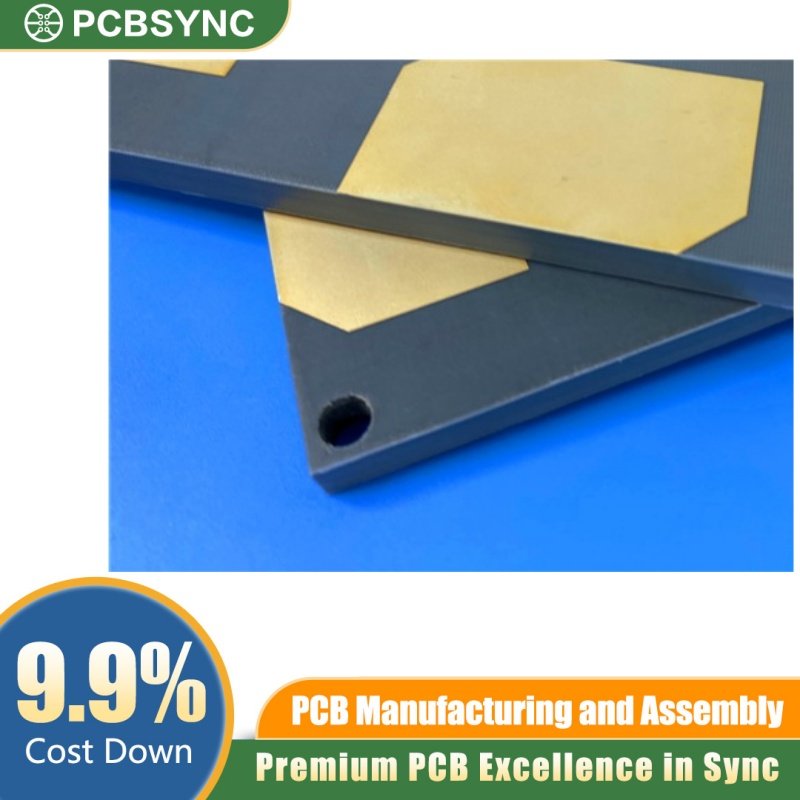
Designed and manufactured by PCBSync, this 2-layer high-frequency PCB is built on genuine Rogers RT/duroid 5870 laminate — one of the industry’s most trusted PTFE-based substrates for demanding RF, microwave, and millimeter-wave circuits. Every element of this board, from the heavy 3oz copper layers to the 100μ” hard gold plating, is specified for engineers who refuse to compromise on signal integrity, thermal stability, or long-term reliability.
Why RT/duroid 5870?
Rogers RT/duroid 5870 is a glass microfiber-reinforced PTFE composite engineered specifically for high-frequency stripline and microstrip applications. With an exceptionally low dielectric constant (Dk) of 2.33 ± 0.02 at 10 GHz and an ultra-low dissipation factor (tan δ) of just 0.0012, this material delivers the lowest electrical loss of any reinforced PTFE laminate on the market. The randomly oriented glass microfibers ensure isotropic performance, meaning your circuits maintain uniform electrical characteristics regardless of signal direction — critical for complex antenna feeds, couplers, and broadband distribution networks.
Unlike standard FR-4, RT/duroid 5870 maintains consistent Dk across a wide frequency spectrum, eliminating the dispersion effects that degrade signal quality in broadband and wideband systems. Its moisture absorption rate of less than 0.02% guarantees stable electrical performance even in high-humidity or outdoor environments, while its inherent chemical resistance simplifies fabrication and ensures long service life.
Board Specifications at a Glance
Substrate: Rogers RT/duroid 5870 (PTFE/glass microfiber composite) Layer Count: 2 layers Board Thickness: 1.6mm Copper Weight: 3oz (105μm) — ideal for high-current RF power stages and improved thermal dissipation Surface Finish: 100μ” (2.54μm) electrolytic hard gold plating — delivers superior contact resistance, excellent solderability, and outstanding resistance to oxidation and wear Dielectric Constant (Dk): 2.33 ± 0.02 @ 10 GHz Dissipation Factor (tan δ): 0.0012 @ 10 GHz
Built for High-Stakes Applications
This board configuration is purpose-built for systems where failure is not an option. Typical deployment scenarios include:
Aerospace & Defense — Military radar arrays, missile guidance receivers, electronic warfare modules, and satellite transponder circuits all demand the thermal stability and signal purity that RT/duroid 5870 provides. The 3oz copper enhances heat spreading in high-power transmit stages, while 100μ” gold plating ensures reliable wire bonding and connector mating across thousands of thermal cycles.
5G & Telecommunications Infrastructure — Point-to-point digital radio links, base station antenna feeds, and millimeter-wave backhaul modules benefit from the substrate’s low-loss characteristics at frequencies well into the Ku-band and beyond.
Test & Measurement — Calibration standards, reference transmission lines, and precision RF fixtures require the dielectric uniformity and long-term stability that RT/duroid 5870 is known for.
Medical RF Systems — High-frequency imaging equipment and diagnostic instruments operating in the microwave spectrum rely on consistent, low-noise substrates to maintain measurement accuracy.
Why 3oz Copper and 100μ” Gold?
The heavy 3oz copper cladding goes far beyond standard 1oz designs. Thicker copper reduces I²R losses in high-current RF power amplifier traces, improves thermal conductivity away from active devices, and lowers DC resistance in bias networks — all of which translate directly to better system efficiency and reduced operating temperatures.
The 100μ” hard gold surface finish is the industry benchmark for high-reliability interconnects. It provides a dense, non-porous barrier against corrosion, ensures repeatable low-resistance contact at edge connectors and test points, and supports both gold wire bonding and standard solder reflow processes. For boards that will be inserted and removed repeatedly, or that must survive decades in the field, this level of gold plating is essential.
PCBSync Quality Assurance
Every board ships with full electrical testing, impedance verification, and dimensional inspection. Our manufacturing process is optimized for PTFE-based laminates, ensuring clean etching, precise registration, and void-free plating on a substrate that requires specialized handling compared to conventional materials.
Order your RT/duroid 5870 high-reliability RF boards from PCBSync today. Whether you need prototype quantities for design validation or production volumes for deployment, we deliver the material quality and fabrication precision your RF systems demand.