When it comes to high-frequency military radar systems, material selection can make or break mission-critical performance. The Rogers RT/duroid 5880 substrate has earned its reputation as the go-to choice for defense contractors and aerospace engineers who demand uncompromising signal integrity at microwave frequencies.
Why RT/duroid 5880 Dominates Military Radar Design
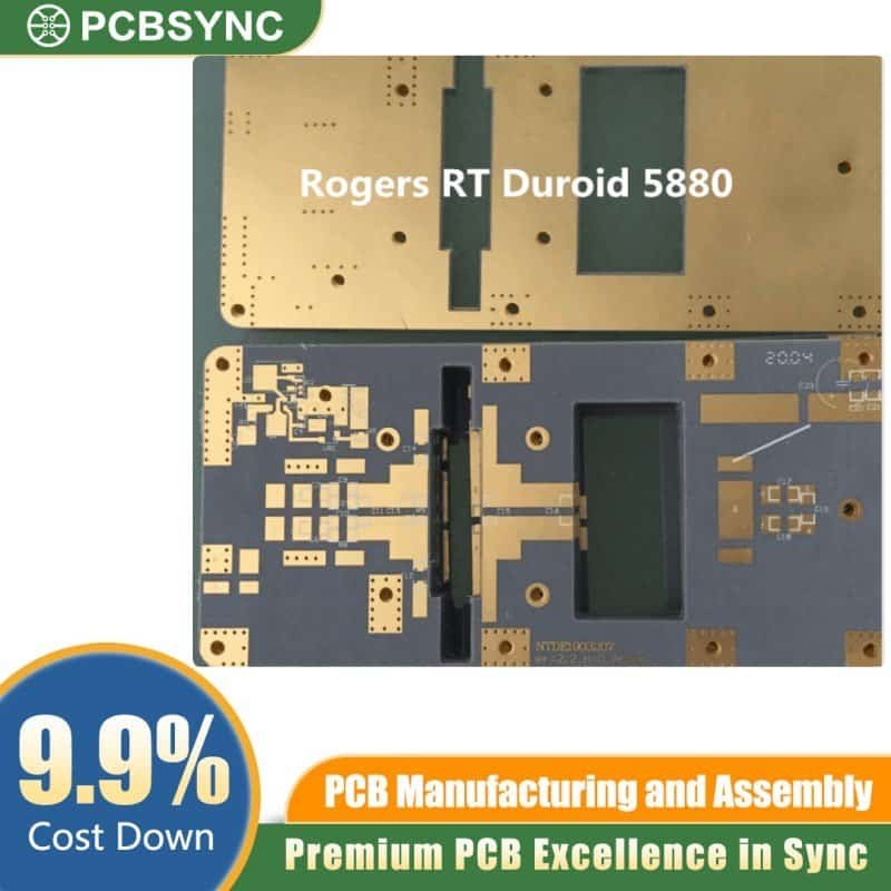
This PTFE-based composite material delivers a remarkably stable dielectric constant of 2.20 across the entire X-band and Ku-band spectrum. Unlike FR-4 or other standard laminates, RT/duroid 5880 maintains consistent electrical properties from -55°C to +125°C—essential for radar arrays operating in extreme environments from Arctic surveillance stations to desert combat zones.
The 1.6mm thickness specification provides the mechanical rigidity needed for phased array antennas while maintaining the precise impedance control that 50-ohm transmission lines require. This thickness strikes the perfect balance between structural integrity and electrical performance, preventing warpage during thermal cycling while supporting tight via aspect ratios.
4-Layer Stack-Up Architecture
Military radar PCBs demand sophisticated layer configurations. The 4-layer design typically features dedicated ground planes that provide superior EMI shielding and return path integrity. Signal layers are strategically positioned to minimize crosstalk between adjacent antenna elements—critical when you’re tracking multiple targets simultaneously at ranges exceeding 100 kilometers.
The 1oz copper weight ensures adequate current-carrying capacity for power distribution networks feeding active components like GaN amplifiers and phase shifters. This copper thickness also supports fine-line etching down to 4-mil traces, enabling dense routing in compact radar modules where space comes at a premium.
ENIG Surface Finish: Built for Reliability
Electroless Nickel Immersion Gold (ENIG) isn’t just about aesthetics. This surface finish provides multiple operational advantages for military applications. The nickel barrier layer prevents copper migration, while the thin gold layer ensures excellent solderability even after extended storage periods. ENIG also offers superior wire bonding characteristics for hybrid assemblies incorporating MMIC chips.
Unlike HASL finishes that create uneven surfaces, ENIG delivers the flatness required for high-density BGA packages and fine-pitch components common in modern radar receivers. The finish withstands multiple reflow cycles without degradation—important when rework becomes necessary on these high-value assemblies.
Real-World Performance Metrics
In operational radar systems, RT/duroid 5880 PCBs demonstrate insertion loss below 0.5 dB at 10 GHz, outperforming alternative substrates by significant margins. The material’s low dissipation factor (0.0009) translates directly to improved receiver sensitivity and extended detection ranges.
Military qualification testing confirms these boards survive 500+ thermal cycles per MIL-STD-810, resist moisture absorption below 0.02%, and maintain dimensional stability under sustained vibration loads. These aren’t marketing claims—they’re verified performance characteristics that keep radar systems operational when failure isn’t an option.
Manufacturing Considerations
Fabricating RT/duroid 5880 PCBs requires specialized equipment and expertise. The material machines differently than standard FR-4, demanding carbide tooling and controlled depth routing to prevent delamination. Reputable manufacturers maintain tight process controls for layer registration, typically achieving ±2 mil alignment across all four layers.
For procurement teams specifying these boards, expect lead times of 3-4 weeks for prototype quantities and rigorous IPC-6012 Class 3 inspection protocols. The investment pays dividends in field reliability and system performance that cheaper alternatives simply cannot match.