Inquire: Call 0086-755-23203480, or reach out via the form below/your sales contact to discuss our design, manufacturing, and assembly capabilities.
Quote: Email your PCB files to Sales@pcbsync.com (Preferred for large files) or submit online. We will contact you promptly. Please ensure your email is correct.
Notes: For PCB fabrication, we require PCB design file in Gerber RS-274X format (most preferred), *.PCB/DDB (Protel, inform your program version) format or *.BRD (Eagle) format. For PCB assembly, we require PCB design file in above mentioned format, drilling file and BOM. Click to download BOM template To avoid file missing, please include all files into one folder and compress it into .zip or .rar format.
CAM350 Manual: Complete User Guide & Documentation [2026]
Finding a comprehensive CAM350 manual that actually explains how to use this powerful CAM software can be frustrating. The official documentation exists, but it’s scattered across multiple sources, and many engineers end up learning through trial and error. After spending years working with CAM350 in production environments—processing everything from simple two-layer boards to complex HDI designs—I’ve compiled this complete user guide covering everything from installation to advanced analysis techniques.
This CAM350 manual serves as your go-to reference for understanding the software interface, mastering essential commands, configuring settings properly, and troubleshooting common issues. Whether you’re a new user trying to get started or an experienced CAM engineer looking for specific command references, this documentation covers the core functionality you’ll need daily.
CAM350, developed by DownStream Technologies (now part of Siemens), is the industry-standard computer-aided manufacturing software for PCB post-processing. It bridges the gap between PCB design and fabrication, allowing engineers to import, verify, edit, analyze, and export manufacturing data.
The software handles multiple critical functions: Gerber file import and verification, Design Rule Checking (DRC), Design for Manufacturing (DFM) analysis, netlist comparison, panelization, NC drill/mill editing, and manufacturing output generation. Without proper understanding of these capabilities—which this CAM350 manual provides—engineers risk releasing flawed data to fabrication.
Before diving into functionality, understanding proper installation ensures smooth operation. Current versions require modern Windows systems with adequate resources.
Current System Requirements (Version 15.x)
Requirement
Specification
Operating System
64-bit Windows 10 or Windows 11
Processor
2 GHz or faster (multi-core recommended)
Memory
8-16 GB RAM minimum
Disk Space
500 MB for installation, additional for project files
Display
1920×1080 resolution minimum recommended
License
Node-locked or floating network license
Installation Process Overview
The CAM350 installation uses a wizard-based approach. Key steps include:
Run the DownStream installation package
Accept the license agreement
Choose installation type (Typical, Custom, or License Only)
Configure license options (node-locked or network)
Complete installation and verify license checkout
For network installations, the license manager (FlexNet) must be installed on a designated server. The license file contains your hostID—either a MAC address, USB dongle serial number, or virtual machine UUID. This CAM350 manual recommends documenting your hostID location for future reference: check Home > Options > License Usage within the software, or locate the license.dat file in C:\DownStreamTech\LicenseManager.
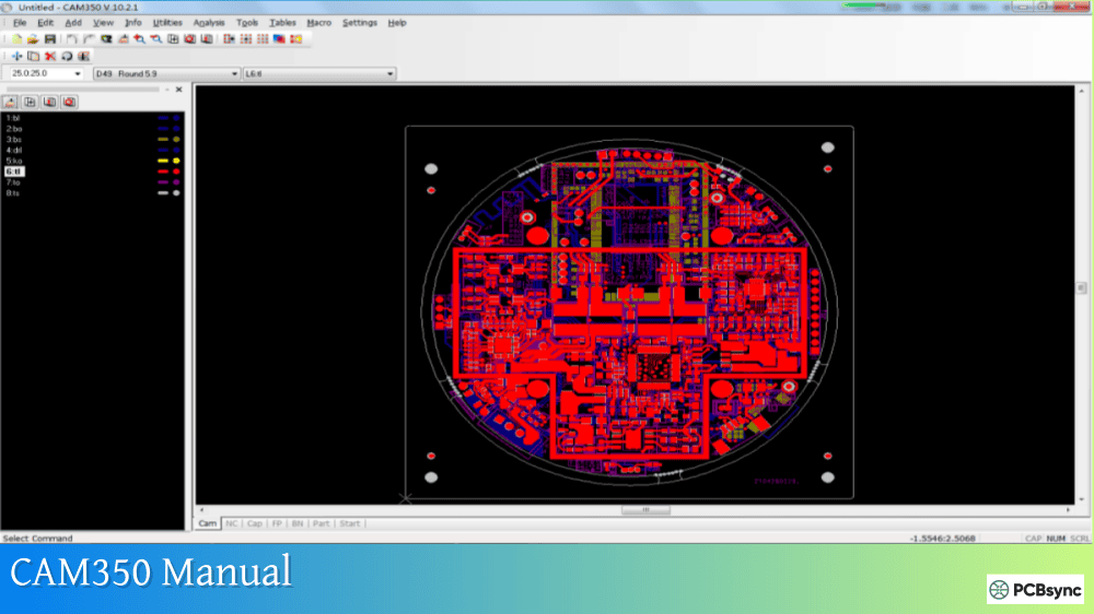
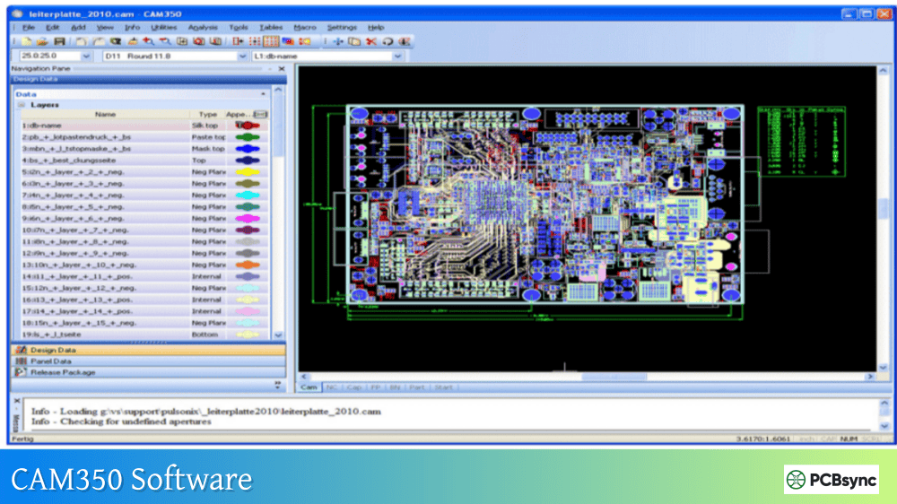
CAM350 User Interface Reference
Understanding the interface is fundamental to productive CAM350 usage. The software uses a ribbon-based interface (since version 12.1) organized by functional areas.
Main Interface Components
Component
Description
Location
Ribbon Bar
Function-based command ribbons
Top of window
Navigation Pane
Project explorer, layer list, Dcodes, nets
Left side
Workspace
Main design viewing and editing area
Center
Status Bar
Coordinates, units, mode indicators
Bottom
Layer Bar
Quick layer visibility and selection
Right side or bottom
Ribbon Organization
The ribbon system groups commands by function. As documented in this CAM350 manual, the primary ribbons include:
Home Ribbon: Core operations including file management, layer operations, alignment commands, view controls, and basic editing functions. The Align Layer command (Home | Align Layer) is essential for correcting layer registration issues.
Edit Ribbon: All modification commands—Add, Move, Copy, Delete, Mirror, Rotate, and Change operations. The Edit | Change | Dcode command allows reassignment of aperture codes to selected elements.
Tools Ribbon: Utilities and advanced operations including Draw to Flash conversion, Over/Undersize, Teardrops, Netlist Extract, and the Macro system. Access reports through Tools | Reports including Dcode reports, BOM, Netlist, and Centroid data.
Analyze Ribbon: Verification and analysis functions—DRC, DFM analysis, Netlist Compare, Design Compare, Check Drill, and Copper Area calculations.
Panel Ribbon: Panelization functions for creating manufacturing panels, step and repeat, merge operations, and panel-specific editing.
NC Ribbon: Drill and mill editing capabilities including tool table management, Gerber to Drill conversion, mill path creation, and NC data export.
CAM350 Manual: File Menu Commands
The File menu contains all import, export, and project management functions. This section of the CAM350 manual details essential file operations.
AutoImport is the recommended method for most situations. It scans a directory, identifies file types automatically, and imports all recognized formats. However, drill files often require separate import with explicit format settings to ensure correct interpretation.
Export Operations
Command Path
Function
Output Formats
File > Export > Gerber Data
Gerber file generation
RS-274X, RS-274D
File > Export > Drill Data
NC drill output
Excellon (Leading/Trailing)
File > Export > Composites
Composite layer output
Gerber
File > Export > ODB++
ODB++ package creation
ODB++
File > Export > IPC-2581
IPC-2581 export
IPC-2581
File > Export > DXF
AutoCAD format export
DXF
Project File Management
CAM350 uses .CAM files as its native project format. These files contain all imported data, layer configurations, aperture tables, and project settings. The File > Save command preserves the complete database state. This CAM350 manual emphasizes regular saving—CAM350 does not auto-save, and unsaved work is lost if the application closes unexpectedly.
Edit Menu Commands and Functions
The Edit menu provides all data modification capabilities. Understanding these commands is critical for effective CAM editing.
Basic Edit Commands
Edit > Move: Relocates selected data. Use the coordinate box for precise positioning. Hotkey hint: ‘W’ enables window selection mode for selecting multiple objects.
Edit > Copy: Duplicates selected data. Combined with the coordinate box, enables precise array creation.
Edit > Delete: Removes selected elements. Use Ctrl+Click to deselect accidentally selected items before confirming deletion.
Edit > Mirror: Creates mirrored copies. Important note from this CAM350 manual: mirroring does not automatically remap layers, so flipping a board front-to-back requires manual layer reassignment.
Edit > Rotate: Rotates selected data around a specified point.
Advanced Edit Operations
Edit > Change > Dcode: Reassigns aperture codes to selected flashes or draws. Essential for correcting aperture assignments or creating modified layers.
Edit > Change > Origin > Datum Coordinate: Establishes the design origin point. Critical for consistent panelization and manufacturing output.
Edit > Layers > Align: Corrects layer registration by selecting corresponding points on misaligned layers. Select a reference point, then click the corresponding point on the layer to align.
Edit > Layers > Reorder: Reorganizes layer sequence. Use the Navigation Pane drag-and-drop or this command to establish logical layer ordering.
Edit > Change > Explode: Converts complex objects to primitive elements. Options include Merged Data (converts merge databases to standard data), Parts, Polygons, and Custom Apertures.
Tools and Utilities Reference
The Tools ribbon contains utility functions that transform, optimize, and process CAM data.
Proper netlist extraction requires flashed pads rather than drawn pads. The Tools > Draw to Flash command (previously Utilities > Draw to Flash) converts draw data to flash format. This CAM350 manual notes this is essential preprocessing before netlist comparison—drawn pads may cause false errors in netlist extraction.
Macro System
CAM350’s macro system enables automation of repetitive tasks. Access via Tools > Macros:
The embedded VB Script editor allows creation of custom automation with conditional logic, user dialogs, and database queries. Sample macros are included in the installation for reference.
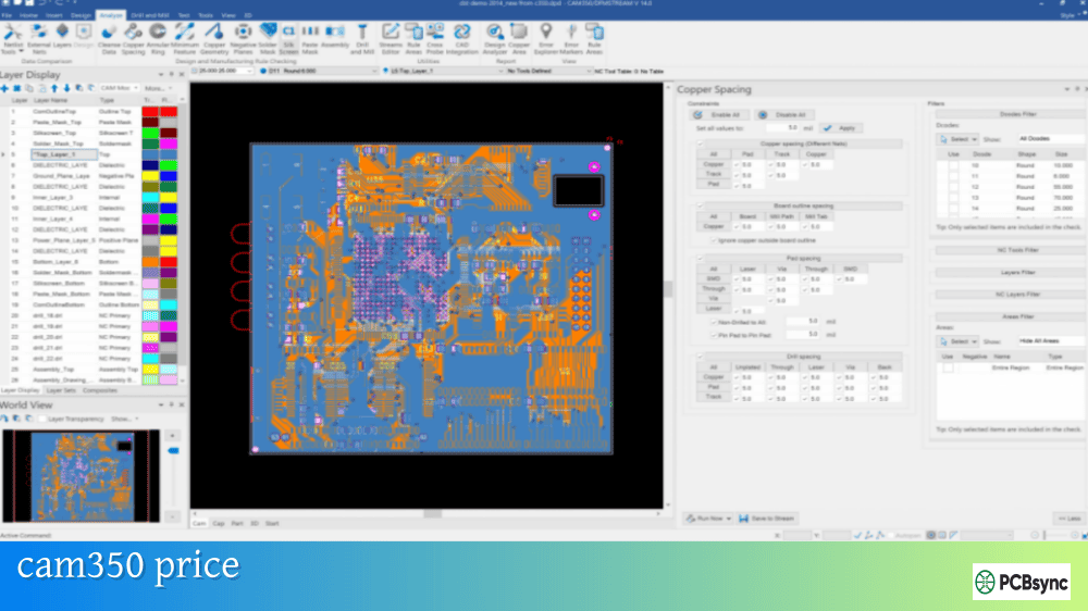
Analysis Functions: DRC and DFM
The Analysis ribbon contains verification functions that identify design issues before manufacturing. This CAM350 manual section covers the critical analysis capabilities.
Design Rule Check (DRC)
DRC verifies geometric rules against specified parameters. Access via Analyze > DRC.
Configure DRC parameters based on your fabricator’s capabilities. Run DRC on all relevant layer combinations—copper-to-copper, copper-to-drill, mask-to-copper, and silkscreen-to-mask.
Design for Manufacturing (DFM) Analysis
DFM analysis goes beyond basic DRC to identify manufacturability issues:
Copper Slivers: Thin copper features prone to lifting
Solder Bridges: Insufficient spacing for solder mask dams
Thermal Relief: Missing or inadequate thermal connections
Mask Slivers: Thin soldermask sections prone to adhesion failure
Antenna Pads: Unconnected internal layer pads
The Streams Rule Check feature allows creation of reusable analysis profiles combining multiple DRC, DFM, and netlist checks into single execution sequences.
Netlist Comparison
Netlist Compare is the definitive verification that Gerber data matches design intent. The process involves:
Import reference netlist (IPC-D-356 format preferred)
Extract netlist from Gerber data (Tools > Netlist Extract)
Run comparison (Analyze > Compare Netlists)
Review results for opens, shorts, and missing nets
This CAM350 manual emphasizes: netlist comparison is the most important pre-fabrication check. It catches connectivity errors that DRC cannot detect.
Design Compare
Design Compare identifies differences between design revisions or between Gerber and intelligent CAD data. Version 15 introduced enhanced auto-alignment capabilities for comparing designs with different origins.
Layer Management and Organization
Effective layer management is fundamental to CAM350 workflow. The Layer Table (accessible via Navigation Pane or Tables > Layers) controls layer properties.
Layer Sets group related layers for operations like netlist extraction with blind/buried vias. Define layer sets via Home > Panes > Layer Sets for designs with complex via structures.
The NC Editor provides drill and mill data creation and modification capabilities. This portion of the CAM350 manual covers essential NC operations.
Drill Operations
Access drill editing through the NC ribbon or by entering NC edit mode:
Add Drill: Place individual drill hits
Add Slot: Create elongated holes
Tool Table: Define and modify drill tool definitions
Check Drill: Verify drill-to-drill spacing and drill-to-feature clearances
Mill Operations
Mill path editing supports panel separation and board outline routing:
Gerber to Mill: Convert Gerber outlines to mill paths
Mill Path Properties: Set feed rate, tool compensation, plunge/extract points
Add Mill Tab: Insert breakaway tabs for panel separation
Tool Table: Define mill tool parameters
NC Data Export
Export drill and mill data via File > Export > Drill Data. Configure format settings carefully—Leading versus Trailing zero suppression, units, and coordinate format must match fabricator requirements.
Panelization Functions
CAM350’s panel functions enable creation of manufacturing arrays. Two primary approaches exist: Fast Array (basic step-and-repeat) and the Panel Editor (full panel design).
Merge Method for Multi-Board Panels
The File > Merge command loads complete CAM350 databases as single units for arrangement:
Prepare individual board databases with proper layer typing
Create new project or use existing as base
File > Merge to load additional databases
Arrange using Edit > Move with coordinate precision
Edit > Change > Explode > Merged Data when layout is finalized
Consolidate layers using Move to Layer function
Panel Editor Workspace
The Panel Editor provides template-based panelization with automated features for adding rails, tooling holes, fiducials, and panel documentation. Access via the Panel ribbon.
Reporting and Documentation
CAM350 generates various reports essential for manufacturing communication.
Available Reports
Report Type
Command Path
Content
Dcode Report
Tools > Reports > Dcodes
Aperture definitions and usage
NC Tool Report
Tools > Reports > NC Tools
Drill/mill tool listing
BOM
Tools > Reports > BOM
Bill of Materials
Netlist Report
Tools > Reports > Netlist
Connectivity listing
Centroid
Tools > Reports > Part Centroids
Component placement coordinates
Copper Area
Analyze > Copper Area
Copper coverage calculation
Printing and Output
File > Print provides hardcopy output with options for separate sheets per layer, fit-to-page scaling, and color/monochrome selection. Export to PDF via File > Export > PDF for electronic documentation.
Keyboard Shortcuts and Hotkeys Reference
Efficient CAM350 operation relies on keyboard shortcuts. This CAM350 manual section provides essential hotkey references.
Navigation Hotkeys
Key
Function
+
Zoom in
–
Zoom out
Ins
Pan to cursor location
Home
Fit all data to screen
Page Up
Increase snap box size
Page Down
Decrease snap box size
Edit Mode Hotkeys
Key
Function
W
Enable window selection mode
C
Toggle crossing/non-crossing selection
I
Toggle inside/outside selection
A
Select all (in edit mode)
S
Toggle grid snap
Z
Object snap to center
Ctrl+Click
Add/remove from selection
Layer and Display Hotkeys
Key
Function
Y
Open Layer Table
A
Open Aperture Table
Q
Query element (shows Dcode info)
Custom Keyboard Shortcuts
Create custom shortcuts via right-click on the ribbon area > Customize. Select Keyboard tab, choose command category, select specific command, and assign desired key combination.
Troubleshooting Common CAM350 Issues
This CAM350 manual section addresses frequently encountered problems and solutions.
The official CAM350 manual and documentation are available through the DownStream Technologies support portal and within the software itself via Help menu. Registered users with active maintenance can access comprehensive PDF documentation, release notes, and technical guides. The built-in help system (F1 or Help > Contents) provides context-sensitive documentation for all commands. Additionally, CAM350 Tech Tips on the DownStream website offer practical tutorials covering specific workflows.
How do I customize keyboard shortcuts in CAM350?
Customizing shortcuts in CAM350 is straightforward. Right-click on any blank area in the ribbon bar and select “Customize.” Navigate to the Keyboard tab, select the command category in the Category dropdown, then select the specific command from the Commands list. Click in the “Press New Shortcut” field and press your desired key combination, then click Assign to save. This CAM350 manual recommends documenting your custom shortcuts since they’re stored in user preferences and may need recreation after reinstallation.
What file formats does CAM350 import and export?
CAM350 supports comprehensive format coverage. Import formats include Gerber (RS-274D, RS-274X, Fire9000, Barco DPF), NC Drill/Mill (Excellon, Sieb & Meyer), IPC netlists (IPC-D-356, IPC-D-356A), ODB++, IPC-2581, DXF, GenCAD, and HPGL. Export formats include Gerber (RS-274X, RS-274D), NC Drill (Excellon), ODB++, IPC-2581, DXF, and additional CAD formats like PADS ASCII and GenCAD depending on configuration. The AutoImport feature automatically detects and imports most common formats from a directory.
How do I resolve license checkout failures?
License issues typically stem from network connectivity, server configuration, or license availability. First, verify network connectivity to your license server. Check that the license manager service is running on the server (use lmtools.exe in the LicenseManager folder). Review the lmgrd.log file for specific error messages. If you see “Licensed number of users already reached,” all available seats are in use—wait for other users to release licenses or request additional seats. For node-locked licenses, verify your hostID matches the license file. Contact DownStream support at support@downstreamtech.com with copies of your license.dat and lmgrd.log files for persistent issues.
What’s the difference between CAM350 configurations (070, 095, 160, 195)?
CAM350 is available in tiered configurations with increasing functionality. The 070 configuration provides basic Gerber viewing with import, view, query, and measurement capabilities. The 095 configuration adds Gerber export, CAM editing, intelligent data import, and basic DRC via Streams. The 160 configuration includes NC editing, panel design, DXF interface, CrossProbing, and ODB++/IPC-2581 export. The 195 configuration provides full DFM analysis, Design Analyzer, Design Compare, and Stencil Designer. Higher configurations like 620 and 815 add advanced features for fabricators including flying probe and bed of nails editors. This CAM350 manual recommends evaluating your specific needs—designers typically need 095 or 160, while fabricators benefit from 195 or higher configurations.
Advanced Features and Workflows
Beyond the core functionality covered earlier in this CAM350 manual, CAM350 includes advanced capabilities that experienced users leverage for complex production scenarios.
Reverse Engineering
CAM350’s Reverse Engineering feature (available in higher configurations) converts unintelligent Gerber data back into structured CAD-like format. The process identifies traces, vias, padstacks, footprints, and nets from raw graphic data. While not a replacement for original CAD files, reverse engineering enables modification of legacy designs where source files no longer exist.
The reverse engineering workflow involves: importing Gerber and drill data, building parts from graphic footprints, extracting netlist connectivity, and exporting to CAD formats like GenCAD or PADS ASCII. This CAM350 manual notes that results require verification and cleanup—automated conversion is a starting point, not a finished result.
CrossProbing with CAD Tools
CrossProbing establishes bidirectional communication between CAM350 and PCB design tools like Cadence Allegro, OrCAD PCB Designer, and Siemens Xpedition. When an element is selected in the CAD tool, the corresponding element highlights in CAM350, and vice versa.
This capability is invaluable for DFM error resolution. After running DFM analysis in CAM350, crossprobing allows direct navigation to error locations in the source CAD tool for correction. Rather than manually locating issues by coordinate, engineers click the error in CAM350 and immediately see the corresponding location in their design tool.
Stencil Designer
Version 15 introduced the Stencil Designer toolkit for creating solder paste stencils. Features include:
Automatic stencil generation from paste mask layers
Interactive pad modification for aperture reduction/expansion
Homeplate and other shape modifications for fine-pitch components
Stencil library creation for reusable pad definitions
Area ratio and aspect ratio analysis for printability
The stencil workflow integrates with CAM350’s standard editing capabilities, allowing engineers to verify paste mask coverage against copper pads and optimize apertures for specific assembly processes.
Automation with VB Scripting
CAM350’s COM-based API enables sophisticated automation beyond simple macro recording. Using Visual Basic, C, C++, or other COM-compatible languages, engineers can:
Create custom dialog interfaces for operator input
Parse design database for specific conditions
Make conditional decisions based on design content
Generate custom reports in any format
Integrate CAM350 into larger automated workflows
Sample scripts included with installation demonstrate common automation patterns. The macro debugger allows step-through execution for development and troubleshooting.
Composite Layers
Composite layers combine multiple physical layers into single output layers. Common applications include:
Creating negative plane layers from positive artwork
Combining solder mask images with multiple clearance types
Generating inner layer images with buried via clearances
The Tables > Composites command defines composite relationships. After editing composites, use Utilities > Convert Composite to flatten the result to a standard layer for export.
Working with Intelligent Data Formats
While Gerber remains common, intelligent formats like ODB++ and IPC-2581 provide significant advantages for CAM processing. These formats include:
Complete layer stackup definitions
Net connectivity information
Component placement and part data
Drill/route specifications
Design intent metadata
This CAM350 manual recommends requesting ODB++ or IPC-2581 from designers when available. Import via File > Import > ODB++ or File > Import > IPC-2581. The additional intelligence enables more accurate netlist comparison, part-aware DFM analysis, and comprehensive manufacturing documentation.
CAM350 Version History and Feature Evolution
Understanding CAM350’s evolution helps users identify feature availability by version and recognize interface differences in documentation from different periods.
Major Version Milestones
Version
Key Changes
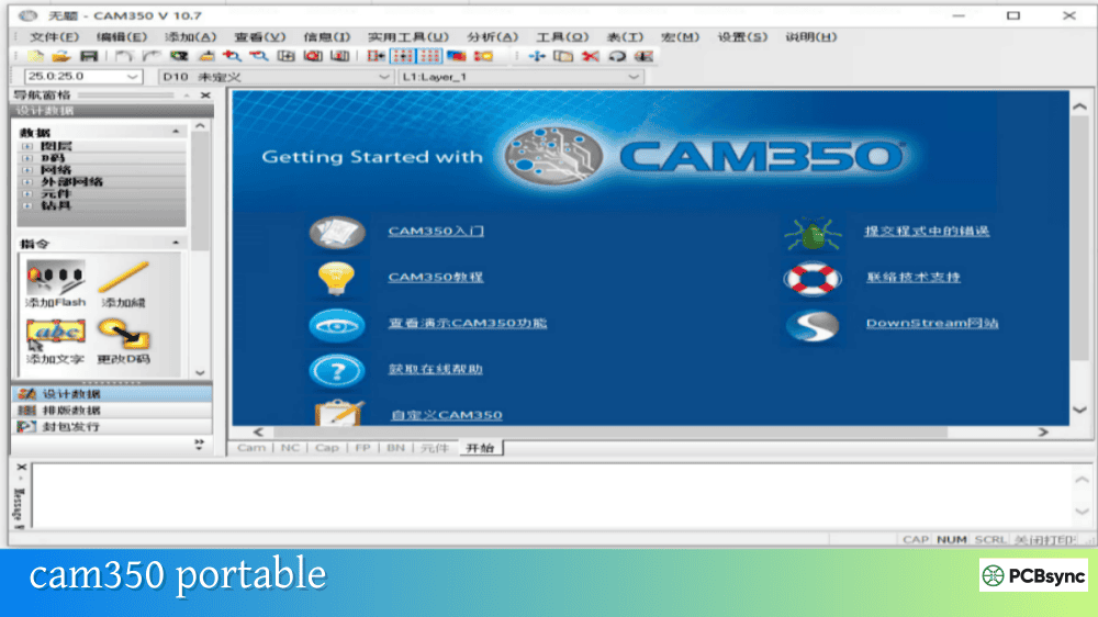
Version 9.x
Classic menu-based interface
Version 10.x
Navigation Pane introduced, enhanced scripting
Version 12.x
Ribbon interface replaces menus, multi-threading
Version 14.x
Updated licensing, enhanced DFM analysis
Version 15.x
Stencil Designer, Auto-Align, Allegro interface
Interface Differences
Users transitioning from older versions should note that Version 12.1 fundamentally changed the interface from traditional menus to ribbons. Command sequences in older documentation reference menu paths (like File > Import > Gerber), while current versions use ribbon notation (File | Import | Gerber Data). The underlying functionality remains consistent, but navigation differs.
Best Practices for CAM350 Workflow
This CAM350 manual concludes with workflow recommendations developed through production experience.
Pre-Import Checklist
Before importing any design:
Verify all expected files are present (Gerber, drill, netlist, readme)
Check file naming conventions to identify layer types
Review readme or fab notes for special instructions
Confirm format specifications (units, precision, zero suppression)
Create backup of original files before processing
Standard Verification Workflow
Import all design files
Verify layer alignment visually
Assign correct layer types
Run DRC with fabricator-specific parameters
Run DFM analysis for producibility issues
Import and compare netlist
Document any issues found
Export verified data with consistent naming
Project Organization
Maintain organized project structures:
Use consistent folder hierarchy for different project stages
Save intermediate CAM files at key workflow points
Document custom apertures and layer configurations
Archive original import files with processed output
Include verification reports with released data
Conclusion
This CAM350 manual has covered the essential knowledge needed to effectively use CAM350 for PCB post-processing. From installation and interface navigation through advanced analysis and panelization, these references provide the foundation for productive CAM operations.
The key to CAM350 proficiency is consistent practice with real design data. Start with basic import and viewing operations, then progressively incorporate DRC, netlist comparison, and editing functions as your confidence grows. The software’s depth rewards investment in learning—engineers who master CAM350 capabilities significantly reduce fabrication issues and accelerate time-to-production.
For ongoing learning, the DownStream Tech Tips archive provides regularly updated tutorials addressing specific workflows and new features. Formal training courses offer structured learning with hands-on exercises. And remember, the built-in help system (F1) remains the most immediate resource for command-specific documentation.
Whether you’re verifying design output before release or preparing complex manufacturing data, CAM350 provides the tools needed to ensure successful PCB fabrication. This CAM350 manual serves as your reference companion for that journey.
Inquire: Call 0086-755-23203480, or reach out via the form below/your sales contact to discuss our design, manufacturing, and assembly capabilities.
Quote: Email your PCB files to Sales@pcbsync.com (Preferred for large files) or submit online. We will contact you promptly. Please ensure your email is correct.
Notes: For PCB fabrication, we require PCB design file in Gerber RS-274X format (most preferred), *.PCB/DDB (Protel, inform your program version) format or *.BRD (Eagle) format. For PCB assembly, we require PCB design file in above mentioned format, drilling file and BOM. Click to download BOM template To avoid file missing, please include all files into one folder and compress it into .zip or .rar format.


