Inquire: Call 0086-755-23203480, or reach out via the form below/your sales contact to discuss our design, manufacturing, and assembly capabilities.
Quote: Email your PCB files to Sales@pcbsync.com (Preferred for large files) or submit online. We will contact you promptly. Please ensure your email is correct.
Notes: For PCB fabrication, we require PCB design file in Gerber RS-274X format (most preferred), *.PCB/DDB (Protel, inform your program version) format or *.BRD (Eagle) format. For PCB assembly, we require PCB design file in above mentioned format, drilling file and BOM. Click to download BOM template To avoid file missing, please include all files into one folder and compress it into .zip or .rar format.
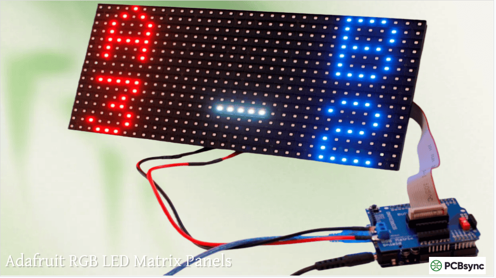
Adafruit RGB LED Matrix Panels: Setup & Display Projects
There’s something deeply satisfying about watching a 64×32 RGB LED panel light up for the first time. All 2,048 pixels blazing in full color, ready to display whatever your code throws at it. I’ve spent countless hours debugging HUB75 timing issues, calculating power budgets, and figuring out why half my LED matrix was showing garbage data. The good news? Adafruit has made this entire process dramatically easier with their ecosystem of panels and driver boards.
This guide covers everything from choosing the right RGB matrix panel to building complete display projects using the Matrix Portal and Matrix Bonnet driver boards.
Unlike NeoPixels or DotStars where each LED has its own controller chip, HUB75 RGB matrix panels are fundamentally different. These panels have no memory—they require constant data streaming to maintain an image. Stop sending data, and the display goes dark.
The panels use a technique called row scanning. At any given moment, only a fraction of the rows are actually lit. The driver rapidly cycles through all rows fast enough that your eye perceives a complete image. This is why these displays need a fast processor continuously dedicated to refreshing them.
How HUB75 Scanning Works
A 64×32 RGB LED panel with 1:16 scan ratio means 2 rows (out of 32) are lit simultaneously. The driver cycles through all 16 row pairs so quickly that persistence of vision creates a solid image. Higher scan ratios (1:8, 1:4) are brighter but require more address pins and processing power.
Scan Ratio
Rows Lit at Once
Address Lines
Brightness
Common Panel Sizes
1:8
2 rows (16px panels)
3 (A, B, C)
High
16×32
1:16
2 rows (32px panels)
4 (A, B, C, D)
Medium
32×32, 64×32
1:32
2 rows (64px panels)
5 (A, B, C, D, E)
Lower
64×64
Adafruit RGB Matrix Panel Options
Adafruit stocks several LED matrix panel sizes, all using the standard HUB75 interface. The main variable is pixel pitch—the distance between LED centers—which affects both physical size and optimal viewing distance.
64×32 RGB LED Panel Variants
The 64×32 RGB LED format is the workhorse of the Adafruit lineup. With 2,048 pixels in a wide aspect ratio, it’s perfect for scrolling text, sports scores, and animated graphics.
The 64×64 matrices use 1:32 scanning, requiring an additional address line (E pin). Both the Matrix Portal S3 and Matrix Bonnet support this, but the Bonnet requires soldering a jumper. Check which pin your specific panel uses for the E line—some use pin 8, others use pin 4 of the HUB75 connector.
Adafruit Matrix Driver Board Options
Here’s where the Adafruit ecosystem really shines. Instead of wiring 13+ data lines by hand and hoping you got them right, these driver boards handle all the signal routing and level shifting.
Matrix Portal S3
The Matrix Portal S3 is Adafruit’s flagship driver for RGB matrix panels. It plugs directly into the back of any HUB75 panel—no wiring, no breadboards, just plug and code.
The Matrix Portal S3 represents a significant upgrade from the original M4 version. The ESP32-S3’s parallel output peripheral handles matrix driving in hardware, freeing up CPU cycles for your actual application code. The 2MB of PSRAM means you can parse large JSON responses from APIs without running out of memory—essential for IoT display projects.
RGB Matrix Bonnet for Raspberry Pi
The Matrix Bonnet transforms any Raspberry Pi into a powerful LED matrix controller. It plugs onto the Pi’s 40-pin GPIO header and provides level-shifted HUB75 output.
Feature
Specification
Compatible Pi Models
Zero, Zero W, 3, 4, 5 (with workaround)
Level Shifters
74AHCT245 (3.3V to 5V)
Power Input
5V via screw terminals
Protection
Reverse polarity, over/under voltage
Assembly
Fully assembled, no soldering
64×64 Support
Yes (solder jumper required)
Panel Chaining
Tested up to 32×128
The Matrix Bonnet includes power protection circuitry that can save your setup from accidental mishaps. I’ve personally connected power backwards before (don’t ask), and the protection circuit did its job.
RGB Matrix HAT with RTC
For projects needing accurate timekeeping without internet access, the RGB Matrix HAT includes a DS1307 Real Time Clock with battery backup.
Feature
HAT
Bonnet
RTC Included
Yes (DS1307)
No
Assembly Required
Some
None
1/32 Scan (64×64)
Rev C only
Yes
Power Protection
Yes
Yes
Price
~$25
~$15
Driver Board Comparison
Feature
Matrix Portal S3
Matrix Bonnet
RGB Matrix HAT
Processor
ESP32-S3
Uses Raspberry Pi
Uses Raspberry Pi
WiFi Built-in
Yes
Via Pi
Via Pi
Standalone Operation
Yes
No (needs Pi)
No (needs Pi)
Programming
CircuitPython/Arduino
Python
Python
Best For
IoT displays, standalone
Linux projects, video
Clock projects
Approximate Cost
$25
$15
$25
Power Requirements and Calculations
RGB matrix panels are power hungry. Each pixel at full white brightness can draw up to 60mA. For a 64×32 RGB LED panel with 2,048 pixels, that’s a theoretical maximum of 123 Amps—though you’ll never actually hit that because of the scanning.
Realistic Power Estimates
Due to row scanning, only a fraction of pixels conduct current simultaneously. The practical formula for power calculation is:
Current (Amps) = Panel Width × 0.12
Panel Configuration
Calculation
Recommended Supply
Single 32×32
32 × 0.12 = 3.84A
5V 4A
Single 64×32
64 × 0.12 = 7.68A
5V 4A (typical content)
Two 64×32 chained
128 × 0.12 = 15.4A
5V 8A minimum
Four 64×32 (2×2)
256 × 0.12 = 30.7A
5V 16A or dual 8A
Power Supply Recommendations
Panel Count
Minimum Supply
Recommended Supply
1 panel (32px wide)
5V 2A
5V 4A
1 panel (64px wide)
5V 4A
5V 4A
2 panels chained
5V 8A
5V 10A
4 panels (grid)
5V 16A
Two 5V 10A supplies
Never power the LED matrix from the Raspberry Pi or Matrix Portal USB port alone. The panels need their own dedicated 5V supply connected to the panel’s power input.
Setting Up the Matrix Portal S3
The Matrix Portal S3 makes setup remarkably straightforward. Here’s the process:
Hardware Assembly
Remove the protective tape from the power standoffs (two amber circles on the back)
Screw the spade connectors from the power cable to the standoffs
Connect the 4-pin power plug from panel to the Matrix Portal power connector
Plug the Matrix Portal directly into the HUB75 input socket on the panel’s left side
Verify the orientation—the white arrow on the panel should point up and right
CircuitPython Installation
Download the latest CircuitPython UF2 from circuitpython.org for MatrixPortal S3
The Matrix Portal S3’s WiFi capability makes it perfect for live sports scores. The ESP-32’s processing power handles large JSON responses from the ESPN API while driving multiple chained 64×32 RGB LED panels.
Components needed:
Matrix Portal S3
Two to four 64×32 RGB LED panels
5V power supply (4A per two panels)
USB-C cable for programming
Network Clock with Weather
Combine the Matrix Portal‘s WiFi with time and weather APIs for a functional desk display. The built-in accelerometer can even detect taps to switch between display modes.
Animated Message Board
CircuitPython’s displayio library makes scrolling text and bitmap animations straightforward. Perfect for retail signage or event notifications.
Retro Game Display
The Matrix Bonnet with Raspberry Pi can emulate retro games and display them on the LED matrix. The Pi’s video output can even be mirrored to the matrix for a unique gaming experience.
Digital Sand Art
Using the Matrix Portal‘s LIS3DH accelerometer, create a mesmerizing digital sand simulation that responds to tilting—a popular project from Adafruit’s tutorials.
Chaining Multiple Panels
Both the Matrix Portal and Matrix Bonnet support connecting multiple panels for larger displays.
Chain vs Tile Configuration
Configuration
Description
Best For
Chain (1×N)
Panels in a row, extending width
Scrolling text, long messages
Tile (N×M)
Grid arrangement
Large images, video walls
Serpentine
Alternating direction per row
Efficient wiring for grids
Memory Requirements for Multiple Panels
Each additional panel increases memory usage significantly. For the Matrix Portal S3 with 2MB PSRAM, practical limits are:
Can I use an Arduino UNO with a 64×32 RGB LED panel?
No, the Arduino UNO lacks sufficient RAM and speed for 64×32 RGB LED panels. The UNO can only drive 32×16 panels without double buffering. For 64×32 panels, use an Arduino Mega (with modifications), or better yet, switch to a Matrix Portal S3 or Raspberry Pi with Matrix Bonnet for much better performance and easier setup.
Why is my LED matrix flickering or showing wrong colors?
Several factors cause display issues. First, check your power supply—insufficient current is the most common culprit. A 64×32 RGB LED panel needs a solid 4A at 5V. Second, verify your wiring is connected to the INPUT connector, not OUTPUT. Third, for the 2.5mm pitch panels (Product ID 5036), green and blue channels are swapped—use the color_order parameter in your code to fix this.
How do I connect multiple panels together for a larger display?
Chain panels by connecting the OUTPUT of one panel to the INPUT of the next using the included IDC ribbon cable. Each panel needs its own power connection—don’t daisy-chain power. In your code, specify the total width (panels × 64 for 64-wide panels). For grid configurations, use serpentine wiring where alternating rows are flipped, and configure the tile_down parameter accordingly.
What’s the difference between the Matrix Portal S3 and the Matrix Bonnet?
The Matrix Portal S3 is a standalone controller with built-in WiFi, processor, and memory—perfect for IoT projects that don’t need a full computer. The Matrix Bonnet requires a Raspberry Pi but gives you access to Linux, Python, and all the Pi’s capabilities including video playback and complex processing. Choose the Matrix Portal for dedicated displays and the Matrix Bonnet for projects needing more computing power or existing Pi integration.
How much power does my RGB matrix display actually need?
Use the formula: Current = Panel Width × 0.12 Amps. A single 64-pixel-wide panel needs about 7.68A maximum, but typical graphics use about half that. For reliable operation, use a 5V 4A supply for each 64×32 RGB LED panel. When chaining multiple panels, add the current requirements together. Always use dedicated 5V supplies—never try to power matrices from USB ports or the Pi’s 5V rail.
Building Your Matrix Display
Starting with Adafruit matrix panels and driver boards eliminates the most frustrating parts of RGB matrix projects—wiring mistakes, level shifting issues, and library configuration headaches. Whether you choose the standalone Matrix Portal S3 for WiFi-connected displays or the Matrix Bonnet for Raspberry Pi projects, the ecosystem provides a clear path from concept to working display.
My recommendation for first-time builders: grab a Matrix Portal S3 and a single 64×32 RGB LED panel. The plug-and-play setup means you can have colorful pixels lighting up within minutes of unboxing. Once you’ve got the basics working, expand to multiple panels, add sensors via STEMMA QT, or build out that sports scoreboard you’ve been planning.
The LED matrix ecosystem has matured significantly. What once required custom PCBs and extensive debugging now comes down to plugging in cables and uploading code. That’s a win for anyone who wants to focus on building cool projects rather than fighting with hardware.
Inquire: Call 0086-755-23203480, or reach out via the form below/your sales contact to discuss our design, manufacturing, and assembly capabilities.
Quote: Email your PCB files to Sales@pcbsync.com (Preferred for large files) or submit online. We will contact you promptly. Please ensure your email is correct.
Notes: For PCB fabrication, we require PCB design file in Gerber RS-274X format (most preferred), *.PCB/DDB (Protel, inform your program version) format or *.BRD (Eagle) format. For PCB assembly, we require PCB design file in above mentioned format, drilling file and BOM. Click to download BOM template To avoid file missing, please include all files into one folder and compress it into .zip or .rar format.


