Inquire: Call 0086-755-23203480, or reach out via the form below/your sales contact to discuss our design, manufacturing, and assembly capabilities.
Quote: Email your PCB files to Sales@pcbsync.com (Preferred for large files) or submit online. We will contact you promptly. Please ensure your email is correct.
Notes: For PCB fabrication, we require PCB design file in Gerber RS-274X format (most preferred), *.PCB/DDB (Protel, inform your program version) format or *.BRD (Eagle) format. For PCB assembly, we require PCB design file in above mentioned format, drilling file and BOM. Click to download BOM template To avoid file missing, please include all files into one folder and compress it into .zip or .rar format.
If you’ve ever tried to design a shield or carrier board for an Arduino in Altium Designer, you know the frustration. You open your schematic, search for “Arduino Uno” in the component libraries, and find… nothing. The standard Altium libraries don’t include Arduino boards as components, which means you either need to find a third-party Altium Designer Arduino Library or create one yourself.
After spending countless hours hunting down reliable Arduino libraries and creating my own when I couldn’t find what I needed, I’ve put together this comprehensive guide. Whether you need an Arduino Uno footprint for a custom shield, a Nano schematic symbol for an embedded project, or a complete Mega 2560 library for a multi-board design, you’ll find what you need here.
When prototyping with Arduino, most engineers work with jumper wires and breadboards. But when it’s time to move from prototype to production, you need a proper PCB that interfaces with your Arduino board. This is where having a proper Altium Designer Arduino Library becomes essential.
Common Use Cases for Arduino Libraries in Altium
Designing Custom Shields: Arduino shields stack on top of the main board and add functionality like motor control, displays, or wireless communication. Your shield PCB needs a footprint that matches the Arduino header positions exactly.
Creating Carrier Boards: When integrating an Arduino Nano or Pro Mini into a larger system, you need a carrier board with proper mounting holes and pin headers. The schematic symbol helps you wire connections correctly, while the footprint ensures physical fit.
Multi-Board System Design: Altium Designer excels at multi-board projects. Having Arduino libraries lets you include development boards in your system-level design, complete with 3D models for enclosure design.
Design Documentation: Even if you’re not designing the Arduino board itself, including it in your schematic provides complete documentation of your system’s electrical connections.
Arduino Board Specifications Reference
Before downloading or creating libraries, understanding each board’s specifications helps ensure you get the right footprint dimensions and pin counts.
These dimensions are critical for footprint accuracy. A footprint with incorrect header spacing will result in a shield that doesn’t fit, wasting time and money on board respins.
Where to Download Altium Designer Arduino Libraries
Finding quality Arduino libraries for Altium can be challenging. Here are the most reliable sources I’ve used over the years.
GitHub Repositories
GitHub hosts several community-created Altium Designer Arduino Library collections. These are typically free and include both schematic symbols and PCB footprints.
Repository
Boards Included
Features
sajjsamm/arduino-footprint-altium
Uno, Mega
Schematic + Footprint, ready to import
ehsunmotamedi/Arduino-Nano-Altium-Library
Nano
Complete library with SchLib and PcbLib
marcopol0/Library-Arduino-Nano-Altium
Nano
GPL licensed, includes footprint
matthiasbock/Altium-Libraries
Multiple Arduino boards
Large library collection with 3D models
Mehdi-KHALFALLAH/My-Arduino-UNO-Design
Uno
Complete project files with documentation
Download Instructions for GitHub Libraries:
Navigate to the repository page
Click the green “Code” button
Select “Download ZIP”
Extract the ZIP file to your Altium libraries folder
In Altium Designer, go to Components → File-based Libraries Preferences
Add the extracted .SchLib and .PcbLib files
SourceForge Arduino Library Collection
SourceForge hosts the “Altium Library Arduino” project, which contains libraries for various Arduino boards and common components used in Arduino projects. This collection is regularly updated and includes components beyond just the Arduino boards themselves.
Component Search Engines
Several online platforms provide free component libraries that can be imported directly into Altium Designer:
Platform
Features
Arduino Coverage
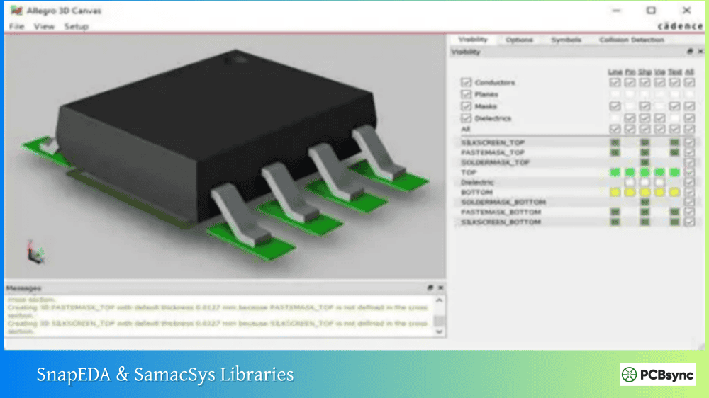
SnapEDA (SnapMagic Search)
Free symbols, footprints, 3D models
Nano, Uno, Mega, Pro Mini
SamacSys (Component Search Engine)
Library Loader plugin for Altium
Various Arduino boards
Ultra Librarian
CAD models for multiple formats
Limited Arduino selection
Octopart
Part search with CAD model links
Links to other sources
Using SnapEDA for Arduino Libraries:
Visit snapeda.com and search for “Arduino Nano” or your desired board
Select the component from the search results
Choose “Altium” as your export format
Download the library files
Import the .SchLib and .PcbLib into your Altium project
Manufacturer Part Search in Altium Designer
Altium’s built-in Manufacturer Part Search connects to Altium 365 and partner databases. While Arduino boards aren’t always available here, you can often find the individual components used on Arduino boards, which helps if you’re designing an Arduino clone.
How to Import Arduino Libraries into Altium Designer
Once you’ve downloaded your Altium Designer Arduino Library files, importing them correctly ensures they work properly in your projects.
Importing Integrated Libraries (.IntLib)
Integrated libraries combine schematic symbols and footprints into a single compiled file:
Open Altium Designer
Navigate to Components panel
Click the three-line menu icon and select File-based Libraries Preferences
In the Installed tab, click Install
Browse to your .IntLib file and select it
Click Close to finish
Importing Separate Schematic and PCB Libraries
Many Arduino libraries come as separate .SchLib (schematic) and .PcbLib (footprint) files:
Open your project in Altium Designer
Right-click the project in the Projects panel
Select Add Existing to Project
Navigate to and select both the .SchLib and .PcbLib files
The libraries now appear under your project
Alternatively, for global access across all projects:
Go to Components panel
Open File-based Libraries Preferences
Click Install and select your library files
These libraries will now be available in all projects
Verifying Library Installation
After importing, verify your libraries work correctly:
Open the Components panel
Search for “Arduino” in the search box
You should see your imported components
Double-click a component to preview the symbol and footprint
Verify the footprint dimensions match the actual board
Creating Your Own Arduino Library in Altium Designer
Sometimes available libraries don’t meet your needs—maybe the footprint uses the wrong pad sizes, or the schematic symbol doesn’t include all the pins you need. Creating your own library ensures accuracy and lets you customize the component to your requirements.
Creating the Schematic Symbol
Start by creating a new schematic library:
Select File → New → Library → Schematic Library
Save it with a descriptive name like “Arduino_Boards.SchLib”
Right-click in the library and select Tools → New Component
Name it according to the board (e.g., “ARDUINO_UNO_R3”)
For the Arduino Uno symbol, you’ll need to place pins for:
Pin Group
Pins
Function
Power
VIN, 5V, 3.3V, GND (x3)
Power supply connections
Digital I/O
D0-D13
Digital input/output pins
Analog Inputs
A0-A5
Analog input pins
Special
RESET, AREF, IOREF
Reference and control pins
Communication
SDA, SCL
I2C interface pins
To add pins:
Select Place → Pin or press P, P
Before placing, press Tab to open pin properties
Set the designator (D0, D1, etc.) and name
Set electrical type (I/O for most pins, Power for power pins)
Place pins and draw a rectangular body around them
Organize pins logically—power pins on one side, digital I/O on another, analog inputs grouped together. This makes schematics more readable.
Creating the PCB Footprint
The footprint requires precise dimensions from Arduino’s official documentation:
Select File → New → Library → PCB Library
Save it as “Arduino_Boards.PcbLib”
Right-click and select Tools → New Blank Component
Name it to match your schematic symbol
For the Arduino Uno footprint:
Header Placement:
Digital header (D0-D13): 8 pins + 6 pins with 0.1″ (2.54mm) spacing
Power header: 6 pins with 0.1″ spacing
Analog header (A0-A5): 6 pins with 0.1″ spacing
Critical Dimensions:
Board outline: 68.6mm x 53.4mm
Header positions measured from board edge per Arduino reference design
Mounting hole positions: Reference Arduino’s CAD files for exact locations
To place pads:
Select Place → Pad or press P, P
Set pad properties: Through-hole, 1mm drill, 1.6mm diameter for standard headers
Use the grid (Ctrl+G) set to 2.54mm for accurate header pin spacing
Place pads in rows matching header positions
Add a board outline on the mechanical layer and mounting holes if needed.
Linking Symbol to Footprint
Connect your schematic symbol to the PCB footprint:
Add documentation to your libraries for future reference:
In the schematic symbol, add a component description
Include links to Arduino’s official documentation
Note any modifications from standard pinouts
Record the source of dimensional data
Useful Resources for Arduino Altium Libraries
Official Arduino Resources
Resource
URL
Content
Arduino Hardware Documentation
docs.arduino.cc/hardware
Official pinouts and specifications
Arduino GitHub Hardware
github.com/arduino
Original Eagle design files
Arduino Store
store.arduino.cc
Board specifications and datasheets
Community Library Sources
Resource
Description
Altium Community Forum
User-shared libraries and discussions
FEDEVEL Academy
Free Altium library for Arduino projects
PCBWay Community
User-contributed libraries and tutorials
EEVblog Forum
Electronics community with shared resources
Component Search Tools
Tool
Best For
SnapEDA
Free verified footprints and symbols
SamacSys Library Loader
Direct import into Altium
Ultra Librarian
Multiple EDA format export
Octopart
Part research and CAD model links
Frequently Asked Questions
Can I use Arduino libraries from Eagle in Altium Designer?
Yes, Altium Designer can import Eagle libraries. Since Arduino’s original designs were created in Eagle, you can import these directly. Go to File → Import Wizard, select “Eagle PCB Design Files” and follow the prompts. The import process converts Eagle schematic symbols and footprints to Altium format, though you may need to clean up some details after import.
Are these Arduino libraries free to use in commercial projects?
Most community-created Arduino libraries on GitHub are released under open-source licenses like GPL or MIT, which permit commercial use. However, always check the specific license for each library. Arduino’s own design files are open-source, and derivatives are generally permitted for commercial use. When in doubt, create your own library from publicly available specifications.
Why don’t standard Altium libraries include Arduino boards?
Standard Altium libraries focus on discrete components like resistors, capacitors, ICs, and connectors. Development boards like Arduino are complete assemblies rather than individual components. Additionally, Arduino boards have many variants (Uno R3, Nano, Mega, etc.) that would require extensive library maintenance. The community fills this gap with shared libraries.
How do I add a 3D model to my Arduino footprint?
To add a 3D model: First, obtain a STEP file of the Arduino board from sources like GrabCAD. In your PCB footprint editor, select Place → 3D Body. Choose “Generic STEP Model” and browse to your STEP file. Position the model to align with your pads and board outline. Use the rotation and offset parameters to fine-tune placement. Save the footprint to include the 3D model.
What’s the difference between .SchLib, .PcbLib, and .IntLib files?
These are Altium’s library file formats: .SchLib (Schematic Library) contains schematic symbols—the visual representations used in circuit schematics. .PcbLib (PCB Library) contains footprints—the physical pad layouts for PCB design. .IntLib (Integrated Library) is a compiled file combining both schematic symbols and PCB footprints into a single, linked package. Integrated libraries ensure symbols and footprints stay synchronized but require recompilation when updated.
Final Thoughts on Arduino Libraries for Altium
Having a reliable Altium Designer Arduino Library collection saves significant time when designing Arduino-based products. Whether you download existing libraries from GitHub and SnapEDA or create your own from Arduino’s specifications, the key is verifying accuracy before committing to fabrication.
Start with well-maintained community libraries for common boards like the Uno and Nano. For specialized boards or when you need specific customizations, invest the time to create your own libraries following the guidelines above. Document everything, maintain consistent naming, and always verify footprints against physical hardware.
The Arduino ecosystem’s open-source nature means you’ll find resources for virtually every board variant. Combined with Altium Designer’s powerful library management and 3D visualization, you can confidently design professional products built on Arduino’s proven platform.
Inquire: Call 0086-755-23203480, or reach out via the form below/your sales contact to discuss our design, manufacturing, and assembly capabilities.
Quote: Email your PCB files to Sales@pcbsync.com (Preferred for large files) or submit online. We will contact you promptly. Please ensure your email is correct.
Notes: For PCB fabrication, we require PCB design file in Gerber RS-274X format (most preferred), *.PCB/DDB (Protel, inform your program version) format or *.BRD (Eagle) format. For PCB assembly, we require PCB design file in above mentioned format, drilling file and BOM. Click to download BOM template To avoid file missing, please include all files into one folder and compress it into .zip or .rar format.


