Inquire: Call 0086-755-23203480, or reach out via the form below/your sales contact to discuss our design, manufacturing, and assembly capabilities.
Quote: Email your PCB files to Sales@pcbsync.com (Preferred for large files) or submit online. We will contact you promptly. Please ensure your email is correct.
Notes: For PCB fabrication, we require PCB design file in Gerber RS-274X format (most preferred), *.PCB/DDB (Protel, inform your program version) format or *.BRD (Eagle) format. For PCB assembly, we require PCB design file in above mentioned format, drilling file and BOM. Click to download BOM template To avoid file missing, please include all files into one folder and compress it into .zip or .rar format.
After spending 15 years designing flex circuits for defense programs, I’ve learned that MIL-PRF-50884 is both essential and frequently misunderstood. This specification governs flexible and rigid-flex printed wiring boards for military applications, and getting it wrong can mean costly redesigns or failed qualification testing. Whether you’re a design engineer specifying flex circuits for an avionics program or a procurement specialist sourcing qualified suppliers, this comprehensive guide covers everything you need to know about MIL-PRF-50884.
MIL-PRF-50884 is a United States Department of Defense (DoD) performance specification that establishes qualification and performance requirements for flexible and rigid-flex printed wiring boards with or without plated-through holes. The specification is administered by the Defense Logistics Agency (DLA) Land and Maritime division, which serves as the qualifying activity for manufacturers seeking to supply compliant products to the military.
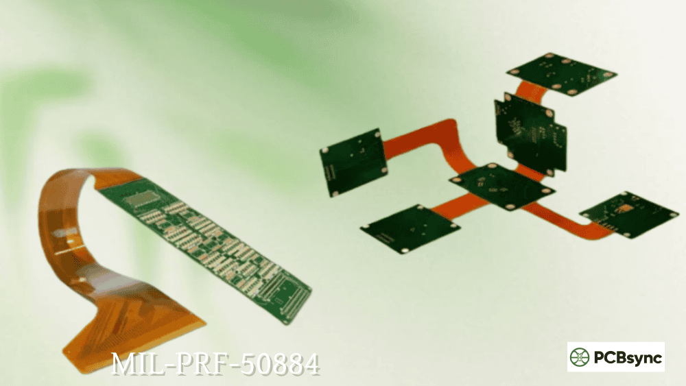
The full title of the specification is “Printed Wiring Board, Flexible or Rigid-Flex, General Specification For.” Unlike rigid PCB specifications, MIL-PRF-50884 specifically addresses the unique challenges of circuits that must bend, flex, or fold during installation or operation—capabilities that are critical in space-constrained military applications where traditional wiring harnesses won’t fit.
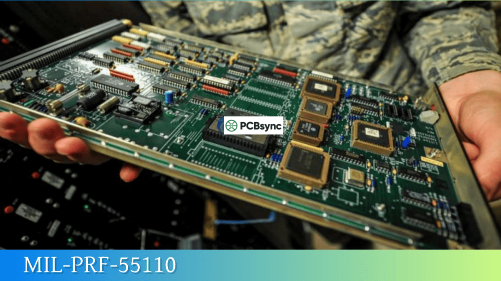
Flexible and rigid-flex printed wiring boards covered by this specification are intended primarily for use in ground support, airborne, and shipboard electronic equipment. They eliminate high-density hand wiring in applications where space is limited and compact packaging is essential for mission success.
MIL-PRF-50884 Current Status and Revision History
Here’s something critical that trips up many engineers new to military specifications: MIL-PRF-50884 has been declared “Inactive for New Design” since February 28, 1999. For new designs, the DoD directs manufacturers to use MIL-PRF-31032 instead.
However, this doesn’t mean MIL-PRF-50884 is obsolete. The specification remains actively maintained for legacy programs and replacement purposes. The current revision is MIL-PRF-50884H, which superseded Revision G (dated July 28, 2020). The DLA continues to maintain qualified supplier databases and update the specification as needed.
Revision
Date
Key Changes
MIL-P-50884E
November 2008
Last revision under original designation
MIL-PRF-50884F
March 2014
Changed to performance specification format
MIL-PRF-50884G
July 2020
Updated appendices and test requirements
MIL-PRF-50884H
Current
Canceled legacy appendices A, B, C; retained D and E
The transition to the “PRF” designation (replacing “P”) signifies that the document is now formally classified as a performance specification. Requirements are expressed in terms of how boards must perform rather than prescriptive manufacturing methods, giving manufacturers flexibility in achieving compliance.
MIL-PRF-50884 Board Types and Classifications
MIL-PRF-50884 categorizes flexible and rigid-flex boards into four distinct types based on their construction complexity:
Combines rigid and flexible sections with plated-through holes
Understanding these classifications matters for qualification purposes. Qualification of Type 4 (the most complex) automatically extends to cover all other types. Type 3 qualification extends to Types 2 and 1. This hierarchical structure allows manufacturers to demonstrate capability at the highest complexity level and receive credit for simpler constructions.
Use Classifications (A vs. B)
Beyond board type, MIL-PRF-50884 further classifies boards by their intended use:
Use Class
Description
Typical Application
Use A
Flex-to-install
Circuit bends during installation only, remains static afterward
Use B
Dynamic flex
Circuit undergoes repeated flexing during normal operation
Use B applications face significantly more stringent testing requirements because the board must survive thousands (sometimes hundreds of thousands) of flex cycles without conductor failure. Applications like continuously rotating radar antennas or articulating robotic arms fall into this category.
Grade Designations (R vs. U)
The specification also includes rework grade designations:
Grade
Description
Grade R
Reworkable—design allows component replacement and repair
Grade U
Non-reworkable—not intended for field-level repair
Grade designation affects inspection criteria and influences design decisions about component placement and test point accessibility.
MIL-PRF-50884 Technical Requirements for Flex and Rigid-Flex PCBs
Let me walk through the technical requirements that differentiate military flex circuits from commercial-grade products.
Material Requirements for Military Flex PCBs
Material selection is foundational to meeting MIL-PRF-50884 requirements. The specification references base materials that must conform to applicable material specifications as defined in the master drawing.
Flexible Base Materials:
Material
Properties
Typical Applications
Polyimide (Kapton)
High temperature resistance (-269°C to +400°C), excellent chemical resistance
Aerospace, high-reliability defense
Polyester (PET)
Lower cost, good flexibility
Commercial, some ground support
Polyethylene Naphthalate (PEN)
Improved temperature range over PET
Mid-range applications
For military applications, polyimide dominates because of its exceptional thermal stability and long-term reliability. Adhesiveless constructions (where copper is directly bonded to the polyimide without adhesive layers) are strongly preferred for high-reliability applications because they eliminate Z-axis coefficient of thermal expansion (CTE) mismatch issues that can cause delamination.
Rigid Section Materials (for Type 4 rigid-flex):
The rigid portions typically use FR-4 or high-Tg polyimide materials that meet MIL-PRF-31032 requirements. Material selection must consider the lamination cycle compatibility between rigid and flexible sections.
Bend Radius Requirements
One of the most critical design parameters in flex circuit design is minimum bend radius. Violating bend radius requirements is a leading cause of flex circuit failure in military applications.
Configuration
Minimum Bend Radius
Notes
1-2 layer flex (static)
6× total flex thickness
For Use A applications
3+ layer flex (static)
12× total flex thickness
For Use A applications
Dynamic flex (Use B)
10× total flex thickness (minimum)
Some applications require 100×
For example, a 0.005″ (5 mil) thick single-layer flex would require a minimum bend radius of 0.030″ for static installations. However, if that same circuit must flex repeatedly during operation, the minimum radius increases to 0.050″ or more depending on the required flex cycle life.
Plated-Through Hole Requirements
For Type 2, 3, and 4 boards with plated-through holes, MIL-PRF-50884 specifies requirements for:
Hole Placement: Plated-through holes must be positioned at least 0.050″ (50 mils) from any flex-to-rigid transition zone to prevent cracking under mechanical strain. Vias placed too close to bend areas will fail during thermal cycling or mechanical flexing.
Annular Ring: Military specifications demand larger minimum annular rings than commercial standards. The exact requirements are specified in the master drawing but are typically more stringent than IPC Class 3.
Copper Plating: Hole wall plating thickness must meet minimum requirements and demonstrate adequate ductility to survive thermal cycling without cracking.
Production screening requires 100% electrical testing of all circuits. Qualification testing adds more stringent requirements performed on test specimens at approved laboratories.
Environmental Testing Requirements
Military flex circuits must survive environmental conditions that would destroy commercial products:
Test
Purpose
Typical Requirements
Moisture and Insulation Resistance
Humidity exposure
96 hours at 95% RH, 40°C
Thermal Shock
Temperature cycling
-65°C to +125°C (or higher)
Flexural Endurance
Bend cycle survival
Varies by Use class
Resistance to Soldering Heat
Assembly survivability
Multiple solder exposure cycles
Vibration
Mechanical stress survival
Per MIL-STD-810
The flexural endurance test is particularly critical for Use B (dynamic flex) applications. Test specimens must survive specified bend cycles at controlled radius without conductor failure.
Qualification under MIL-PRF-50884 has evolved significantly. The current revision streamlines the process through integration with MIL-PRF-31032.
QML Pathway (Primary Route)
The primary qualification pathway now requires certification to MIL-PRF-31032’s Qualified Manufacturers List (QML) program. From the specification:
“All printed wiring boards manufactured and delivered in compliance with this document shall be produced in accordance with the approved quality management plan. QML product assurance procedures shall be revised to address changes from the previous revision of this specification.”
This means manufacturers must:
Establish and maintain a Technical Review Board (TRB)
Demonstrate process capability through qualification testing
Submit ongoing production samples to DLA-certified laboratories
Undergo periodic DLA audits
Maintain listing on QML-31032
Legacy QPL Pathway
The traditional Qualified Products List (QPL) pathway through Appendix A has been canceled in the current revision. Manufacturers who held QPL listings must transition to the QML program to maintain qualification.
If you’re certified to MIL-PRF-31032 with flex/rigid-flex technology qualified, you can produce boards to MIL-PRF-50884 requirements through the transitional QPL/QML program.
MIL-PRF-50884 vs. IPC-6013: Understanding the Differences
Design engineers often ask about the relationship between MIL-PRF-50884 and IPC-6013 (Qualification and Performance Specification for Flexible Printed Boards). Here’s how they compare:
Aspect
MIL-PRF-50884
IPC-6013 Class 3/3A
Governing Body
DoD/DLA
IPC (Industry consortium)
Qualification
DLA-administered QML
Manufacturer-customer agreement
Material Requirements
Specified materials
Performance-based
Testing
DLA-certified laboratories
Customer-approved facilities
Ongoing Audits
Required by DLA
Per customer requirements
Defect Criteria
Stricter rejection
Some allowances
Cost
Higher (audits, lab testing)
Lower
Important: IPC-6013 Class 3A (the aerospace addendum) meets many of the same performance requirements as MIL-PRF-31032 and is accepted by some government agencies as a commercial off-the-shelf (COTS) equivalent. However, if your contract specifically requires MIL-PRF-50884 compliance, IPC-6013 alone won’t satisfy the requirement.
For designs that must meet MIL-PRF-50884 or MIL-PRF-31032 requirements, follow the IPC-2223 design specification recommendations for flex and rigid-flex layouts.
These applications share common requirements: operation in extreme temperatures (typically -55°C to +125°C or beyond), resistance to shock and vibration, immunity to electromagnetic interference, and zero tolerance for field failures.
Design Considerations for MIL-PRF-50884 Compliant Flex PCBs
Based on years of working with military flex circuits, here are the design practices that separate successful programs from problematic ones:
Trace Routing in Flex Areas
Route traces perpendicular to the bend axis when possible
Avoid 90-degree trace bends; use curved or 45-degree angles
Use wider trace widths in flex areas to reduce stress concentration
Stagger traces across the flex area rather than stacking them
Maintain uniform copper distribution to prevent stress points
Via Placement
Keep vias at least 50 mils from flex-to-rigid transition zones
Avoid vias in any area that will bend
Use anchor vias or tie-downs at transition areas for mechanical reinforcement
Consider via-in-pad restrictions for high-density packages
Coverlay and Stiffener Design
Extend coverlay beyond the flex-rigid transition for reliable lamination
Use stiffeners to protect component areas and provide ZIF connector interfaces
Specify stiffener materials (FR-4, polyimide, or stainless steel) appropriate to the application
Allow adequate adhesive flow areas for stiffener attachment
Thermal Management
Place high-power components on rigid sections where heat sinking is possible
Use thermal vias in rigid areas to conduct heat to copper planes
The official specification PDF is available for free download from the DLA portal. Commercial document services also provide copies, typically with additional search and update notification features.
Selecting a MIL-PRF-50884 Qualified Manufacturer
When sourcing military flex circuits, verify these qualifications:
Certification Requirements
QML-31032 Certification with flex/rigid-flex technology qualified
AS9100 Certification for aerospace quality management
ITAR Registration for defense-related products
Nadcap Accreditation (for some programs)
Technical Capabilities to Evaluate
Capability
Importance
Polyimide material experience
Critical for high-reliability applications
Adhesiveless construction capability
Reduces CTE mismatch failures
Laser drilling/routing
Enables fine features and controlled depth drilling
What is your typical lead time for prototype versus production quantities?
Frequently Asked Questions About MIL-PRF-50884
What is the difference between MIL-PRF-50884 and MIL-PRF-31032?
MIL-PRF-31032 is the umbrella specification covering all PCB types (rigid, flexible, and rigid-flex) and is the required specification for new designs. MIL-PRF-50884 specifically addresses flexible and rigid-flex boards and is now maintained exclusively for legacy programs and replacement applications. Qualification to MIL-PRF-50884 requirements is achieved through MIL-PRF-31032 certification with appropriate technology qualification.
Can I still specify MIL-PRF-50884 on new designs?
Technically, the specification is “inactive for new design” since 1999. For new programs, you should specify MIL-PRF-31032 with the appropriate slash sheet (MIL-PRF-31032/3 for flexible or MIL-PRF-31032/4 for rigid-flex). However, if you’re supporting an existing program with drawings that reference MIL-PRF-50884, the specification remains valid and maintained.
What testing is required for MIL-PRF-50884 qualification?
Qualification testing includes visual and dimensional inspection, electrical testing (continuity, isolation, dielectric withstanding voltage), mechanical testing (flexural endurance, thermal shock), and environmental testing (moisture resistance, soldering heat resistance). All qualification testing must be performed at DLA-certified laboratories. The specific test matrix depends on board type and use classification.
How does bend radius affect MIL-PRF-50884 compliance?
Bend radius is critical to flex circuit reliability. The minimum bend radius depends on the number of conductor layers and the use classification. For static (Use A) applications, minimum radius is 6× thickness for 1-2 layers and 12× for 3+ layers. Dynamic (Use B) applications require at least 10× thickness, with some high-cycle applications requiring 100× or more. Violating minimum bend radius is a common cause of flex circuit failure.
What is the relationship between MIL-PRF-50884 and IPC-6013?
IPC-6013 is the commercial industry specification for flexible printed boards, maintained by IPC. While IPC-6013 Class 3A meets many of the same performance requirements as military specifications and is accepted as a COTS equivalent for some applications, it does not automatically satisfy MIL-PRF-50884 contractual requirements. The key differences involve qualification pathway (DLA versus industry), ongoing audit requirements, and specific material/testing mandates. If your contract specifies MIL-PRF-50884, you need a QML-31032 qualified manufacturer.
Conclusion: Navigating MIL-PRF-50884 Successfully
Working with MIL-PRF-50884 requires understanding both the specification itself and its relationship to the broader military qualification ecosystem. While the specification has been inactive for new designs since 1999, it remains vital for supporting the vast installed base of military equipment that relies on flex and rigid-flex circuits.
For new programs, invest the effort to specify MIL-PRF-31032 correctly from the start—it provides comprehensive coverage for all board types under one qualification umbrella. For legacy support, ensure your manufacturing partner holds current QML-31032 certification with appropriate flex/rigid-flex technology qualification.
The unique capabilities of flex and rigid-flex PCBs—space savings, weight reduction, elimination of connectors, and ability to survive dynamic flexing—make them indispensable for modern military electronics. By understanding MIL-PRF-50884 requirements thoroughly and partnering with qualified manufacturers, you can design flex circuits that meet the demanding reliability requirements of defense applications while avoiding costly redesigns and qualification failures.
Remember: in military applications, there’s no substitute for working with experienced flex circuit engineers and qualified manufacturers who understand both the specification requirements and the practical challenges of producing circuits that will perform reliably in combat conditions.
Inquire: Call 0086-755-23203480, or reach out via the form below/your sales contact to discuss our design, manufacturing, and assembly capabilities.
Quote: Email your PCB files to Sales@pcbsync.com (Preferred for large files) or submit online. We will contact you promptly. Please ensure your email is correct.
Notes: For PCB fabrication, we require PCB design file in Gerber RS-274X format (most preferred), *.PCB/DDB (Protel, inform your program version) format or *.BRD (Eagle) format. For PCB assembly, we require PCB design file in above mentioned format, drilling file and BOM. Click to download BOM template To avoid file missing, please include all files into one folder and compress it into .zip or .rar format.


