Inquire: Call 0086-755-23203480, or reach out via the form below/your sales contact to discuss our design, manufacturing, and assembly capabilities.
Quote: Email your PCB files to Sales@pcbsync.com (Preferred for large files) or submit online. We will contact you promptly. Please ensure your email is correct.
Notes: For PCB fabrication, we require PCB design file in Gerber RS-274X format (most preferred), *.PCB/DDB (Protel, inform your program version) format or *.BRD (Eagle) format. For PCB assembly, we require PCB design file in above mentioned format, drilling file and BOM. Click to download BOM template To avoid file missing, please include all files into one folder and compress it into .zip or .rar format.
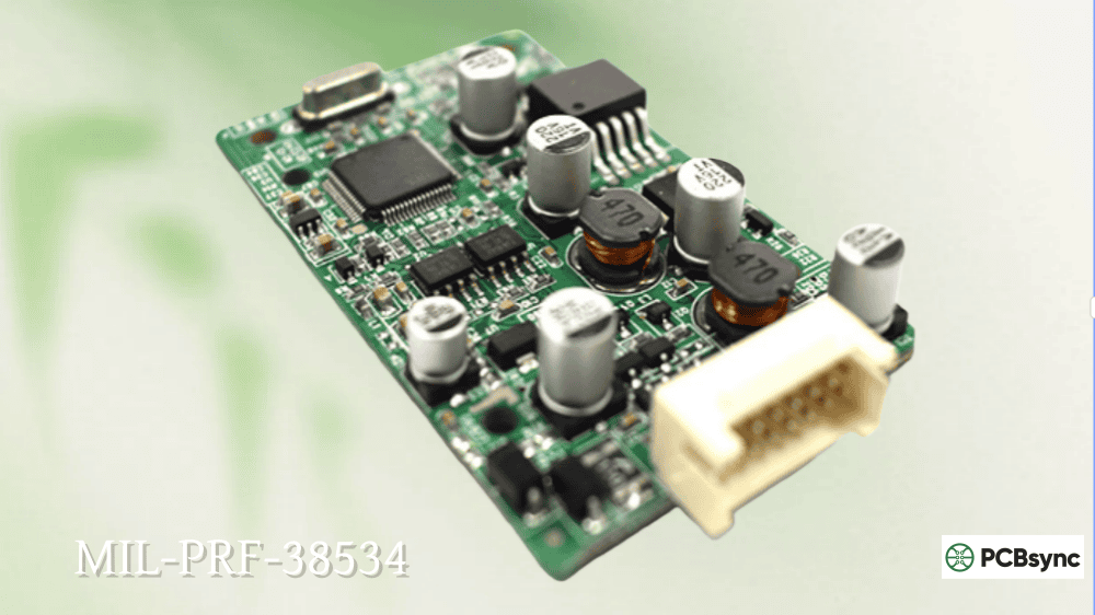
Hybrid microcircuits occupy a unique space in military electronics. When standard monolithic ICs can’t handle the power, when you need custom analog functions, or when radiation hardness matters more than anything else, hybrids become your go-to solution. MIL-PRF-38534 is the specification that governs how these critical components are manufactured and qualified for defense and aerospace applications.
I’ve spent considerable time working with hybrid assemblies on programs where off-the-shelf solutions simply didn’t exist. Custom DC-DC converters, radiation-hardened power drivers, specialized sensor interfaces—these applications almost always point toward hybrid technology. This guide walks through MIL-PRF-38534 from a practical engineering perspective, covering what you actually need to know when designing with or procuring military hybrid microcircuits.
MIL-PRF-38534 is the U.S. Department of Defense performance specification for hybrid microcircuits used in military and aerospace applications. The specification establishes requirements for design, manufacturing, testing, and quality assurance of hybrid assemblies intended for high-reliability applications.
Unlike monolithic integrated circuits covered under MIL-PRF-38535, hybrid microcircuits combine multiple technologies on a single substrate. A typical hybrid might include thick-film or thin-film resistors, bare semiconductor die (unpackaged chips), discrete capacitors, and wire bond interconnections—all integrated into a hermetically sealed package.
Defining Hybrid Microcircuits Under MIL-PRF-38534
The specification defines a hybrid microcircuit as a microcircuit consisting of elements that are formed on or within a substrate, combined with one or more separately attached parts. This distinguishes hybrids from monolithic ICs (single die) and multi-chip modules (which have their own specifications).
Key characteristics of MIL-PRF-38534 hybrid assemblies include:
Substrate-based construction: Ceramic substrates (typically alumina or aluminum nitride) provide the foundation for deposited passive elements and die attachment.
Mixed technology integration: Thick-film, thin-film, or combinations thereof create resistors, conductors, and sometimes capacitors directly on the substrate.
Attached components: Semiconductor die, chip capacitors, and other discrete elements are bonded to the substrate and interconnected.
Hermetic packaging: Most military hybrids use welded or brazed metal packages with glass-to-metal seals for environmental protection.
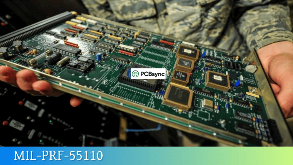
MIL-PRF-38534 Quality Levels and Classifications
Understanding the classification system is essential for specifying the right parts for your application. MIL-PRF-38534 defines quality levels that correspond to different screening intensities and reliability requirements.
Device Classes in MIL-PRF-38534
Class
Quality Level
Primary Applications
Key Requirements
Class K
Highest (Space)
Satellites, spacecraft, strategic systems
Maximum screening, radiation testing, 100% DPA
Class H
High Reliability
Aircraft avionics, missiles, shipboard
Full screening, qualification testing
Class G
Standard Military
Ground tactical, support equipment
Reduced screening requirements
Class D/E/F
Lower grades
Non-critical applications
Minimum compliance
Class K Requirements for Space Applications
Class K hybrids undergo the most rigorous qualification and screening. If you’re working on space programs, expect these additional requirements:
Requirement
Class K Specification
Burn-in duration
320 hours minimum at elevated temperature
Temperature cycling
-65°C to +150°C, 100 cycles minimum
DPA (Destructive Physical Analysis)
Required on samples from each lot
Radiation testing
Total dose and SEE characterization
PIND testing
100% particle impact noise detection
Hermeticity
Fine and gross leak on 100% of units
QML Certification Under MIL-PRF-38534
Similar to MIL-PRF-38535 for monolithic ICs, MIL-PRF-38534 uses the Qualified Manufacturers List (QML) system. Manufacturers earn QML certification by demonstrating their facilities, processes, and quality systems meet DLA requirements.
QML Level
Certification Scope
Audit Frequency
QML-K
Space grade qualification
Annual TCI audit
QML-H
High reliability certification
Annual TCI audit
QML-G
Standard military certification
Annual TCI audit
Once certified, QML manufacturers can self-certify new hybrid designs without individual device qualification—a significant advantage for custom hybrid development programs.
MIL-PRF-38534 Hybrid Construction Technologies
One aspect that makes MIL-PRF-38534 hybrids interesting from an engineering standpoint is the variety of construction technologies permitted. Your choice of technology affects performance, cost, and reliability.
Thick-Film Hybrid Technology
Thick-film is the workhorse technology for military hybrids. Screen-printed pastes are fired onto ceramic substrates to create conductors, resistors, and dielectric layers.
Element
Material System
Typical Specifications
Conductors
Gold, silver, palladium-silver
Sheet resistance: 1-5 mΩ/sq
Resistors
Ruthenium oxide (RuO2)
TCR: ±100 ppm/°C, tolerance: ±1%
Dielectrics
Glass-ceramic compositions
Breakdown: >500V/mil
Overglaze
Glass passivation
Environmental protection
Advantages of thick-film for MIL-PRF-38534 applications:
Cost-effective for moderate volumes
Wide range of resistor values (10Ω to 10MΩ)
Good power handling capability
Laser trimming for precision values
Well-established reliability data
Thin-Film Hybrid Technology
Thin-film hybrids use vacuum deposition (sputtering, evaporation) to create precision passive elements. The tighter tolerances come at higher cost.
Element
Material System
Typical Specifications
Conductors
Gold, aluminum
Sheet resistance: <0.1 Ω/sq
Resistors
Tantalum nitride (TaN), NiCr
TCR: ±25 ppm/°C, tolerance: ±0.1%
Capacitors
Silicon dioxide, tantalum oxide
Tight capacitance tolerance
When to choose thin-film for MIL-PRF-38534 designs:
Precision analog circuits requiring ±0.1% resistors
Note that BeO requires special handling precautions due to toxicity of beryllium dust. Many programs avoid it despite the thermal advantages.
MIL-PRF-38534 Testing and Screening Requirements
The screening and qualification requirements separate military hybrids from their commercial counterparts. Every step exists because of lessons learned from field failures.
Group A Testing (Electrical Verification)
Group A tests verify electrical parameters on samples from each inspection lot.
Test Subgroup
Parameters
Test Conditions
A1
DC parameters at 25°C
Ambient conditions
A2
DC parameters at maximum temperature
Typically +125°C
A3
DC parameters at minimum temperature
Typically -55°C
A4
AC/dynamic parameters
Per device specification
A5
Functional tests
Per device specification
A6
Switching characteristics
Per device specification
Group B Testing (Construction Analysis)
Group B tests evaluate the physical construction and workmanship of the hybrid assembly.
Getting a hybrid design through MIL-PRF-38534 qualification requires attention to detail from the earliest design stages. Here’s practical guidance from programs I’ve worked on.
Design Rules for Military Hybrids
Design Element
Recommendation
Rationale
Die attach
Eutectic or conductive epoxy, void-free
Thermal and mechanical reliability
Wire bond pitch
Minimum 150μm between bonds
Manufacturing yield, inspection access
Bond pad size
Minimum 100μm × 100μm
Bond reliability, rework capability
Resistor spacing
Minimum 250μm from substrate edge
Prevent edge chipping damage
Power derating
50% of rated power at max temp
Long-term reliability
Thermal design
Junction temp <125°C at worst case
Life acceleration factor
Common Design Pitfalls
Inadequate thermal management: I’ve seen hybrids fail qualification because designers didn’t account for power dissipation in the hermetic package. Unlike commercial assemblies that can dissipate heat through convection, sealed hybrids rely on conduction through the package base.
Insufficient clearance for wire bonds: Loop heights and bond-to-bond clearances need to survive constant acceleration testing (typically 20,000g). Design in extra margin.
Wrong die attach material: Gold-silicon eutectic provides the best thermal performance but requires a gold metallization on die backside. Conductive epoxy is more forgiving but has higher thermal resistance.
Ignoring coefficient of thermal expansion (CTE) matching: Large die on alumina substrates can crack during temperature cycling if the CTE mismatch isn’t managed through proper die attach.
MIL-PRF-38534 Part Numbering System
Understanding the part numbering conventions helps when specifying and procuring military hybrids.
Standard Military Drawing (SMD) Format
5962-XXXXXXXHXX
Segment
Meaning
5962
Federal Supply Class for microcircuits
XXXXXXX
Drawing number (7 characters)
H
Quality level (K, H, G)
XX
Package/lead finish designator
Source Control Drawing (SCD) Approach
Many hybrid programs use Source Control Drawings rather than standard military drawings. The SCD defines:
Detailed electrical requirements
Approved manufacturers
Screening requirements
Test methods
Acceptance criteria
This approach provides more flexibility for custom designs while maintaining military quality levels.
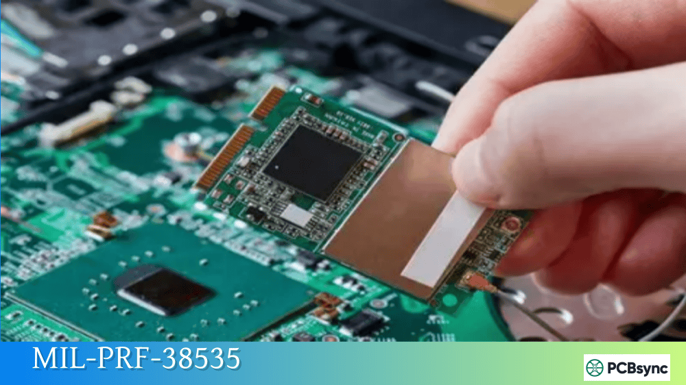
MIL-PRF-38534 vs. MIL-PRF-38535: Key Differences
Engineers sometimes confuse these specifications. Here’s a clear comparison:
What is the main difference between MIL-PRF-38534 and MIL-PRF-38535?
MIL-PRF-38534 covers hybrid microcircuits, which are assemblies containing multiple die and passive components on a ceramic substrate within a single package. MIL-PRF-38535 covers monolithic integrated circuits, which are single semiconductor die. Choose MIL-PRF-38534 when you need custom functionality combining multiple technologies, higher power handling, or integrated passive components that aren’t available in standard monolithic ICs. Hybrids are particularly valuable for power conversion, RF applications, and custom analog circuits where standard parts don’t meet requirements.
How long does it take to qualify a new hybrid design under MIL-PRF-38534?
First article qualification for a new MIL-PRF-38534 hybrid typically takes 6-12 months after design completion. This includes building qualification lots, completing all Group A through D testing, performing destructive physical analysis, and generating qualification documentation. For Class K (space grade) hybrids, add another 3-6 months for extended burn-in, radiation testing, and more extensive DPA requirements. The timeline can be shortened if the manufacturer already has QML certification and the design uses previously qualified materials and processes. Starting with a qualified manufacturer is essential—attempting to qualify both the design and the manufacturer simultaneously can double the schedule.
Can thick-film and thin-film technologies be combined in a MIL-PRF-38534 hybrid?
Yes, combining thick-film and thin-film technologies in a single hybrid is permitted under MIL-PRF-38534 and is sometimes the optimal approach. A common configuration uses thick-film conductors for power routing and component attachment, with thin-film resistor networks for precision analog functions. The thin-film elements typically go on a separate chip resistor that’s attached to the thick-film substrate. This approach leverages the cost advantages of thick-film for non-critical elements while achieving the precision of thin-film where needed. The manufacturer must be qualified for both technologies, and the combination must be documented in the device specification.
What causes most MIL-PRF-38534 hybrid failures during qualification?
Based on qualification programs I’ve been involved with, the most common failure modes are wire bond failures during temperature cycling, hermetic seal failures, and die attach voids causing thermal failures during burn-in. Wire bond issues usually trace to improper bonding parameters or contamination. Seal failures often result from inadequate package preparation or welding parameters. Die attach problems stem from voiding in the attach material or CTE mismatch stress. All three failure modes are preventable with proper process controls. Less common but still significant are failures from electrostatic discharge damage during handling, which highlights the importance of ESD controls throughout the manufacturing flow.
Is radiation testing required for all MIL-PRF-38534 hybrids?
Radiation testing is not automatically required for all MIL-PRF-38534 hybrids—it depends on the quality level and application. Class K (space grade) hybrids typically require radiation characterization including total ionizing dose and single event effects testing because they’re intended for space and strategic applications. Class H and G hybrids don’t require radiation testing unless specifically called out in the device specification for a particular application. If your program has radiation requirements, specify them clearly in the procurement documentation and verify the manufacturer has capability for radiation testing or has relationships with qualified radiation test facilities. Radiation-hardened hybrids use specially selected die and may incorporate design techniques like current limiting to prevent latchup.
Practical Guidance for Working with MIL-PRF-38534
After years of specifying and debugging military hybrids, here are key takeaways:
Engage early with manufacturers. Hybrid development is collaborative. The earlier you involve your QML supplier in the design process, the smoother qualification will go. They know what works and what causes problems.
Don’t underestimate thermal analysis. Hybrids pack a lot of power into small packages. Detailed thermal modeling before committing to a design prevents expensive redesigns later.
Plan for obsolescence. Semiconductor die used in hybrids go obsolete faster than hybrid products. Include die lifetime buys in your program planning.
Document everything. Military hybrid programs generate substantial paperwork. Establish documentation practices from the start, including design rationale, analysis results, and qualification data.
Build margin into your designs. Temperature extremes, vibration, and shock during screening are demanding. Components and interconnects need margin beyond nominal ratings.
MIL-PRF-38534 hybrids remain essential for applications where standard ICs fall short. Understanding the specification, working with qualified manufacturers, and designing for reliability from the start leads to successful programs. The additional effort compared to commercial procurement pays off in systems that perform reliably in the harshest environments military and aerospace applications demand.
Inquire: Call 0086-755-23203480, or reach out via the form below/your sales contact to discuss our design, manufacturing, and assembly capabilities.
Quote: Email your PCB files to Sales@pcbsync.com (Preferred for large files) or submit online. We will contact you promptly. Please ensure your email is correct.
Notes: For PCB fabrication, we require PCB design file in Gerber RS-274X format (most preferred), *.PCB/DDB (Protel, inform your program version) format or *.BRD (Eagle) format. For PCB assembly, we require PCB design file in above mentioned format, drilling file and BOM. Click to download BOM template To avoid file missing, please include all files into one folder and compress it into .zip or .rar format.


