Inquire: Call 0086-755-23203480, or reach out via the form below/your sales contact to discuss our design, manufacturing, and assembly capabilities.
Quote: Email your PCB files to Sales@pcbsync.com (Preferred for large files) or submit online. We will contact you promptly. Please ensure your email is correct.
Notes: For PCB fabrication, we require PCB design file in Gerber RS-274X format (most preferred), *.PCB/DDB (Protel, inform your program version) format or *.BRD (Eagle) format. For PCB assembly, we require PCB design file in above mentioned format, drilling file and BOM. Click to download BOM template To avoid file missing, please include all files into one folder and compress it into .zip or .rar format.
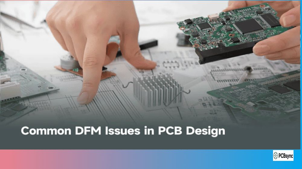
Best DFM Software Tools for PCB Design in 2026: A Practical Guide from the Workbench
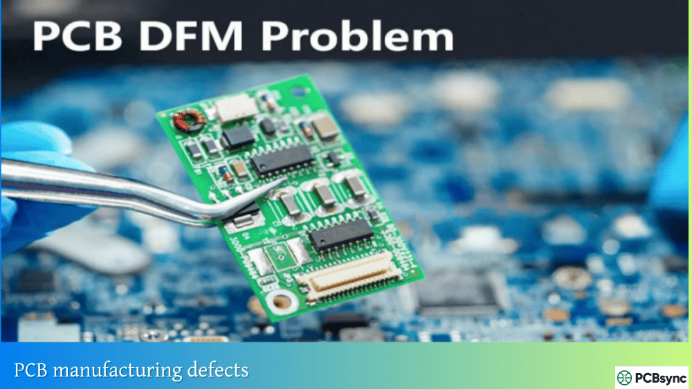
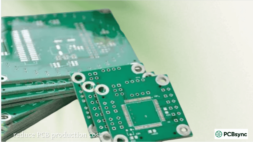
After spending over a decade routing boards and watching designs come back from fab houses with issues that could have been caught earlier, I’ve learned one thing the hard way: your EDA’s built-in design rule check isn’t the same as proper DFM analysis. If you’re still treating manufacturability as an afterthought, you’re probably burning money and time on unnecessary respins.
This guide covers the DFM software tools that actually matter in 2026, based on real-world usage and what I’ve seen work across prototypes, small batches, and production runs. Whether you’re a solo hardware developer or part of a larger engineering team, picking the right DFM tool can mean the difference between a first-pass success and weeks of back-and-forth with your manufacturer.
What Are DFM Software Tools and Why Do They Matter?
DFM software tools (Design for Manufacturing software tools) analyze your PCB design against actual manufacturing constraints before you send files to fabrication. Unlike basic DRC (Design Rule Check) that your EDA software runs, DFM tools evaluate your design against real-world production limitations like etching tolerances, drill capabilities, solder mask registration, and assembly processes.
Here’s the gap most engineers don’t realize exists: your Altium or KiCad DRC knows about electrical correctness. It ensures your traces meet clearance requirements and your nets are connected properly. But it has no idea whether the specific fabricator you’re using can actually produce that 3.5-mil trace with their etching process, or whether your 8-mil drill-to-copper spacing will cause reliability issues.
DFM software tools bridge that gap by importing manufacturer-specific capabilities and running your design against them. The result is fewer engineering change orders, faster time-to-market, and boards that actually work the first time.
Top DFM Software Tools for PCB Design in 2026
The landscape of DFM software tools has shifted significantly. Enterprise solutions still dominate complex applications, but free and cloud-based options have become surprisingly capable. Here’s what’s actually worth your time.
Enterprise-Grade DFM Software Tools
Siemens Valor NPI
Valor NPI remains the industry benchmark for serious DFM analysis. If you’re working on automotive, aerospace, medical devices, or high-density interconnect boards, this is what the big players use.
The tool runs thousands of manufacturing checks and integrates directly with your fabricator’s process capabilities through Siemens’ PCBflow cloud platform. You can analyze FR4, rigid-flex, flex, and even advanced packaging substrates. The component risk assessment feature leverages Siemens’ Valor Parts Library (over 350 billion component records) to flag assembly risks before they become field failures.
The catch? Licensing costs are substantial. Unless you’re doing volume production or working in heavily regulated industries, the ROI calculation gets tricky for smaller operations.
Cadence Allegro with DFM Integration
Allegro’s integrated DFM capabilities have improved considerably. The platform now offers real-time DFM checks during layout, constraint-driven manufacturing rules, and tight integration with Cadence’s simulation ecosystem.
For teams already invested in the Cadence toolchain, this makes sense. The learning curve is steep, but you get signal integrity analysis, power distribution network analysis, and DFM checking in one environment.
Free and Accessible DFM Software Tools
Not everyone needs enterprise licensing. These tools offer legitimate DFM analysis without the budget pain.
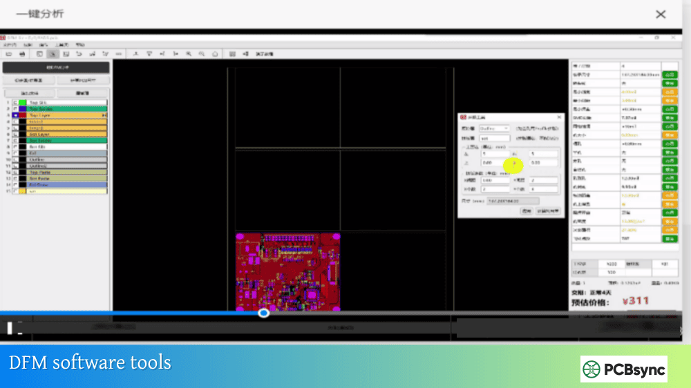
HQDFM by NextPCB
This is probably the most capable free DFM tool available in 2026. HQDFM offers both a web-based viewer and a desktop client with over 1,200 DFM and DFA checks. The desktop version includes BOM comparison, panelization tools, and detailed manufacturing analysis.
What makes it useful: the tool was developed by an actual PCB manufacturer (NextPCB/HuaQiu), so the rules reflect real production constraints rather than theoretical guidelines. You get realistic 3D board visualization, copper-to-edge spacing analysis, drill diameter validation, and acid trap detection.
Import your Gerber, ODB++, or even raw KiCad files, and you’ll see issues flagged with specific locations and severity levels. The PDF export makes it easy to share findings with your team.
JLCDFM
JLCPCB’s web-based DFM tool requires no installation and provides instant analysis. Upload your Gerber files (zip format, max 50MB), and you’ll get feedback on traces, solder masks, drilling, silkscreen, and component assembly.
The analysis is tied to JLCPCB’s manufacturing capabilities, which is actually a benefit if you’re planning to fab there. You’re checking against the exact process constraints your boards will encounter.
Five analysis modules cover the critical areas: trace width and spacing, solder mask bridge detection, drill parameters, silkscreen quality, and component placement issues.
PCBflow by Siemens
Siemens offers a cloud-based version of their Valor technology through PCBflow. While not as comprehensive as the full Valor NPI suite, it provides legitimate DFM analysis with manufacturer-specific capabilities.
The free tier includes DFM reports, interactive visualization, and the ability to connect with manufacturers directly on the platform. It supports ODB++, IPC2581, and Gerber 274x formats. For designers who want Valor-quality analysis without the enterprise commitment, this is worth exploring.
Sierra Circuits Better DFM
Sierra Circuits’ online tool offers a 40-point manufacturability checklist with customizable rule parameters. You can specify your own design rules, indicate plated vs. non-plated holes, and get layer-by-layer PDF outputs.
The tool integrates with their quoting system, so you can immediately see pricing implications of design choices. The netlist comparison feature catches opens and shorts that might survive your EDA’s DRC.
EDA-Integrated DFM Capabilities
Altium Designer
Altium’s rules-driven design engine lets you encode DFM requirements directly into your project. The Constraint Manager allows specification of manufacturing parameters, and DRC runs continuously against those constraints.
The Altium 365 platform adds cloud collaboration features, including a “Send to Manufacturer” function that streamlines the handoff process. While not a standalone DFM tool, the integration makes manufacturing awareness part of your daily workflow.
The 3D ECAD/MCAD tools help catch mechanical interference issues that pure DFM analysis might miss, particularly for boards going into tight enclosures.
KiCad with External DFM Tools
KiCad’s built-in DRC has improved significantly through version 7 and beyond, but it still covers electrical rules rather than manufacturing constraints. The workaround: export your designs and run them through dedicated DFM software tools like HQDFM or JLCDFM.
HQDFM specifically supports direct .kicad_pcb import, eliminating the need to export Gerbers first for initial checks.
DFM Software Tools Comparison Table
Tool
Cost
Best For
Key Strengths
Limitations
Valor NPI
$$$$
Enterprise, regulated industries
Most comprehensive checks, manufacturer integration
Not all DFM software tools check the same things. Here are the critical analyses that matter for real-world manufacturing:
Fabrication Analysis
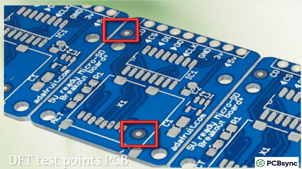
Acid traps form where acute copper angles cause etching problems, leaving excess copper that creates shorts. Your DFM tool should flag these automatically.
Annular ring violations occur when drill registration causes breakout from the pad copper. The difference between your EDA’s pad-to-drill calculation and actual manufacturing tolerance can surprise you.
Copper-to-edge spacing that’s too tight causes layer delamination and reliability issues. Most fab houses want 10-15 mils minimum, but your DFM tool should check against your specific manufacturer’s requirements.
Trace width and spacing analysis goes beyond your DRC settings to evaluate what’s actually manufacturable at your chosen technology level.
Assembly Analysis
Solder mask bridge detection catches cases where the mask opening between fine-pitch pins is too small for reliable solder dam formation.
Component clearance checking ensures pick-and-place equipment can handle your placement density without interference.
Fiducial placement validation confirms your board can be oriented correctly by automated assembly equipment.
BOM validation against component libraries catches part number errors before you discover the wrong package is being quoted.
How to Integrate DFM Software Tools Into Your Workflow
Running DFM analysis at the end of your design cycle catches problems too late. Here’s a more practical approach:
During component selection: Check footprint compatibility with your fab house’s capabilities. Some DFM software tools include component risk assessment that flags problematic packages early.
After initial placement: Run a quick DFM check before routing. Placement issues are easier to fix before you’ve committed hours to trace routing.
Before design review: Formal DFM analysis should be part of your review checklist, not an afterthought.
Before release to manufacturing: Final DFM validation against your selected fab house’s specific capabilities. This is where manufacturer-specific DFM profiles become critical.
Your choice depends on your specific situation, but these factors matter most:
Manufacturer compatibility: The best DFM analysis uses your actual fab house’s process capabilities. Tools that support manufacturer-specific DFM profiles provide more accurate results than generic rule sets.
File format support: Make sure the tool handles your EDA’s export formats. ODB++ provides richer data than Gerbers, but not all tools support it fully.
Analysis depth: Count the number of checks, but more importantly, look at what categories they cover. Fabrication-only analysis misses assembly issues.
Workflow integration: Cloud tools offer convenience; desktop tools offer more comprehensive analysis. Pick based on how you actually work.
Reporting quality: You’ll need to share DFM findings with manufacturers and team members. Clear, actionable reports save communication time.
Frequently Asked Questions About DFM Software Tools
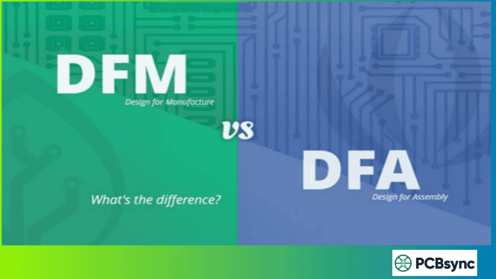
What’s the difference between DRC and DFM analysis?
DRC (Design Rule Check) validates your design against electrical requirements—trace spacing, net connectivity, clearance violations. It ensures your design is electrically correct. DFM (Design for Manufacturing) analysis validates against manufacturing constraints—whether the board can actually be fabricated and assembled with real production equipment. Your EDA’s DRC doesn’t know what drill sizes your fab house supports or whether their etching process can handle your trace geometry.
Are free DFM software tools good enough for production boards?
For most standard technology boards, yes. Tools like HQDFM and JLCDFM cover the critical pcb manufacturing checks that catch common problems. They’re developed by actual PCB manufacturers, so the rule sets reflect real production constraints. However, if you’re working with advanced HDI, flex-rigid, or aerospace/medical applications, enterprise tools like Valor NPI provide more comprehensive analysis and regulatory compliance checking.
How often should I run DFM analysis during PCB design?
At minimum, run DFM checks after placement and before final release. A better approach runs checks iteratively: after initial component selection (for footprint compatibility), after placement (before routing commits), during detailed design review, and as final validation before manufacturing file release. Catching issues early saves significant rework time.
Can DFM software tools replace communication with my manufacturer?
No. DFM tools supplement manufacturer communication; they don’t replace it. Even the best analysis tool uses generalized or manufacturer-provided rules that might not capture every capability nuance. Complex boards, new processes, or tight tolerances still require direct technical discussion with your fab house. Use DFM analysis to catch obvious issues and reduce back-and-forth, not to eliminate collaboration.
Which file format should I use for DFM analysis?
ODB++ provides the richest data for DFM analysis, including layer stack information, net connectivity, and component data in a single package. If your EDA supports ODB++ export, use it. IPC-2581 is another intelligent format gaining adoption. Gerber 274x works for basic analysis but requires separate drill files and lacks embedded design intent information. Some tools like HQDFM can import native KiCad files directly, avoiding export altogether.
Final Thoughts
The DFM software tools landscape in 2026 offers legitimate options at every budget level. Enterprise teams have more powerful analysis than ever through Valor NPI and Allegro integration. Individual designers and small companies can access professional-grade checking through free tools like HQDFM and PCBflow.
The bigger shift is philosophical: treating manufacturability as a design constraint from the start rather than a validation step at the end. The tools exist to support this approach. Whether you’re routing a simple two-layer prototype or a complex 20-layer HDI board, running proper DFM analysis before file release is now table stakes for professional PCB development.
Pick a tool that fits your workflow, learn what its checks actually mean, and make DFM analysis part of your standard process. Your future self—and your manufacturing partners—will thank you.
Meta Description Suggestion:
Discover the best DFM software tools for PCB design in 2026. Compare Valor NPI, HQDFM, PCBflow, and other DFM tools with features, pricing, and download links. Practical guide from a PCB engineer’s perspective.
(155 characters – optimized for search display)
Alternative Meta Description (shorter):
Best DFM software tools for PCB design in 2026: Compare free and enterprise options including HQDFM, Valor NPI, PCBflow. Includes comparison tables and download links.
Inquire: Call 0086-755-23203480, or reach out via the form below/your sales contact to discuss our design, manufacturing, and assembly capabilities.
Quote: Email your PCB files to Sales@pcbsync.com (Preferred for large files) or submit online. We will contact you promptly. Please ensure your email is correct.
Notes: For PCB fabrication, we require PCB design file in Gerber RS-274X format (most preferred), *.PCB/DDB (Protel, inform your program version) format or *.BRD (Eagle) format. For PCB assembly, we require PCB design file in above mentioned format, drilling file and BOM. Click to download BOM template To avoid file missing, please include all files into one folder and compress it into .zip or .rar format.


