Inquire: Call 0086-755-23203480, or reach out via the form below/your sales contact to discuss our design, manufacturing, and assembly capabilities.
Quote: Email your PCB files to Sales@pcbsync.com (Preferred for large files) or submit online. We will contact you promptly. Please ensure your email is correct.
Notes: For PCB fabrication, we require PCB design file in Gerber RS-274X format (most preferred), *.PCB/DDB (Protel, inform your program version) format or *.BRD (Eagle) format. For PCB assembly, we require PCB design file in above mentioned format, drilling file and BOM. Click to download BOM template To avoid file missing, please include all files into one folder and compress it into .zip or .rar format.
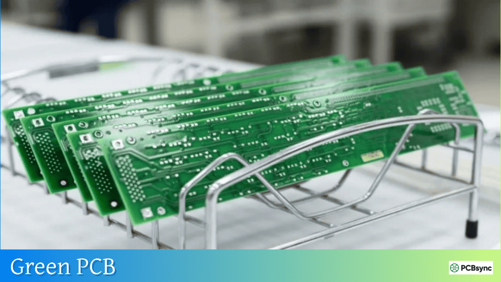
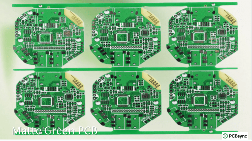
Crack open any electronic device—your laptop, smartphone, router, or TV remote—and you’ll almost certainly find a green circuit board inside. This isn’t coincidence, brand preference, or arbitrary tradition. There are solid technical and economic reasons why green PCB dominates the industry, and understanding these reasons helps you make better decisions about when green is right for your project and when alternatives might make sense.
The green PCB has been the default choice in electronics manufacturing for over five decades. The green color comes from the solder mask—a thin polymer layer that protects copper traces from oxidation and prevents solder bridges during assembly. While solder masks are available in virtually any color today, green remains the overwhelming choice for production boards, prototypes, and everything in between.
The dominance of green PCB isn’t a marketing decision or aesthetic preference—it emerged from practical manufacturing realities in the early days of circuit board production.
Historical Origins of Green Solder Mask
Era
Development
Late 1950s
First epoxy-based solder masks introduced
Early 1960s
Discovery that epoxy formulations naturally cure green
Mid-1960s
Recognition of green’s superior inspection contrast
Late 1960s
Major manufacturers standardize on green
1970s
Economies of scale cement green as default
1980s–Present
Green established as industry standard
The original glass epoxy substrates (FR-4) had a natural greenish tint, and early solder mask formulations using epoxy resins cured to a similar green color. Manufacturers found this color worked well for inspection, and as production equipment was calibrated for green, switching to other colors became increasingly impractical.
Military Influence on Green PCB Standardization
According to industry sources, the U.S. military tested various solder mask colors under adverse conditions and found green performed most reliably. Military specifications required green, and since many PCB manufacturers served both military and commercial customers, green became their standard color. The surplus of green materials made it the most economical choice for all customers.
Technical Advantages of Green PCB
The green PCB offers genuine technical benefits that explain its continued dominance even as alternative colors have become readily available.
Superior Visual Inspection Contrast
Element
Green Contrast
Why It Matters
Copper traces
Excellent
Easy defect detection
Empty spaces
Excellent
Clear distinction from traces
White silkscreen
Excellent
Readable component labels
Solder joints
Good
Quality inspection
Flux residue
Good
Cleanliness verification
Green provides optimal contrast against copper traces (reddish-brown), white silkscreen printing, and the silver/gold of solder joints. This contrast makes visual inspection faster and more accurate, whether performed by humans or automated optical inspection (AOI) systems.
AOI System Optimization
Automated Optical Inspection systems were originally designed and calibrated for green PCB surfaces. These systems often use red light for scanning, and green provides maximum contrast against red wavelengths.
AOI Factor
Green Performance
Red light contrast
Optimal
Defect detection rate
Highest
False positive rate
Lowest
Calibration stability
Best
Historical optimization
Decades of refinement
While modern AOI systems can handle any solder mask color, green remains the baseline against which other colors are measured. Switching colors may require recalibration and can affect inspection accuracy.
Solder Mask Dam Capability
Due to extensive research and development, green PCB solder mask achieves the thinnest coating and smallest solder mask dams of any color.
Color
Minimum Solder Mask Dam
Green
3 mil (0.076 mm)
Blue
3.5 mil (0.089 mm)
Red
3.5 mil (0.089 mm)
Black
4–6 mil (0.10–0.15 mm)
White
4 mil (0.10 mm)
Smaller solder mask dams allow tighter spacing between pads, which matters for fine-pitch components and high-density designs. If your design pushes manufacturing limits, green gives you the most margin.
Reduced Eye Strain During Inspection
Green light falls in the middle of the visible spectrum where human eyes are most sensitive. Workers performing manual inspection experience less eye fatigue with green PCB compared to other colors, particularly during extended shifts.
Color
Eye Strain Level
Manual Inspection Suitability
Green
Lowest
Excellent
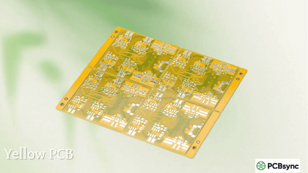
Yellow
Low
Good
Blue
Moderate
Acceptable
Red
Moderate
Acceptable
Black
High
Poor
White
High (glare)
Poor
Cost Advantages of Green PCB
Beyond technical benefits, green PCB offers significant cost advantages that matter for both prototypes and production.
Manufacturing Cost Comparison
Color
Relative Cost
Lead Time Impact
Green
Baseline (lowest)
Standard
Blue
+10–15%
+1–2 days
Red
+10–20%
+1–2 days
Black
+15–25%
+2–3 days
White
+15–25%
+2–3 days
Yellow
+10–15%
+1–2 days
Custom
+20–50%
+5–14 days
Why Green Costs Less
Factor
Green Advantage
Material availability
Always in stock at every fabricator
Production volume
Highest volume = lowest unit cost
Equipment setup
No changeover required
Process optimization
Most refined formulation
Defect rate
Lowest rejection rate
Inspection efficiency
Fastest quality verification
Fabricators maintain large inventories of green solder mask material because it’s their default. Switching to another color requires material changeover, equipment cleaning, and process adjustment—all of which add cost and time.
When to Choose Green PCB
For most applications, green PCB is the right choice. Here’s when green makes the most sense:
Ideal Applications for Green PCB
Application
Why Green Works Best
Production boards
Lowest cost, fastest delivery
Prototypes
Best inspection capability
Fine-pitch designs
Smallest solder mask dams
Cost-sensitive projects
Most economical option
Quick-turn orders
Always available
High-reliability products
Most mature process
Complex multilayer boards
Easiest inspection
Green PCB Design Considerations
Consideration
Green Specification
Silkscreen color
White (standard), black, yellow
Minimum trace visibility
Excellent down to 3 mil
Pad-to-pad spacing
7 mil minimum with 3 mil dam
Surface finish compatibility
All finishes
RoHS compliance
Standard
When to Consider Alternative Colors
While green PCB is optimal for most applications, specific situations justify choosing other colors.
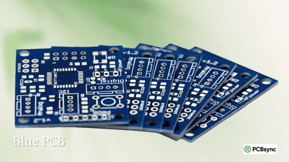
Blue PCB Applications
Use Case
Rationale
Arduino-style boards
Brand recognition
LCD backplane boards
Reduces visual distraction
High-frequency circuits
Some formulations offer better dielectric properties
Silkscreen-heavy designs
Excellent white text contrast
Blue is the second most popular color and offers reasonable contrast, though inspection requires more care than green.
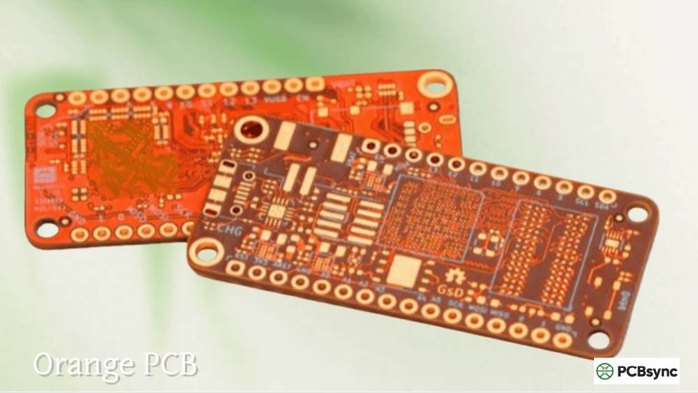
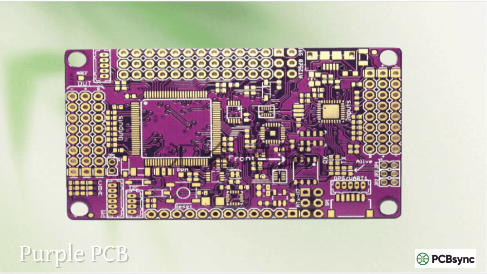
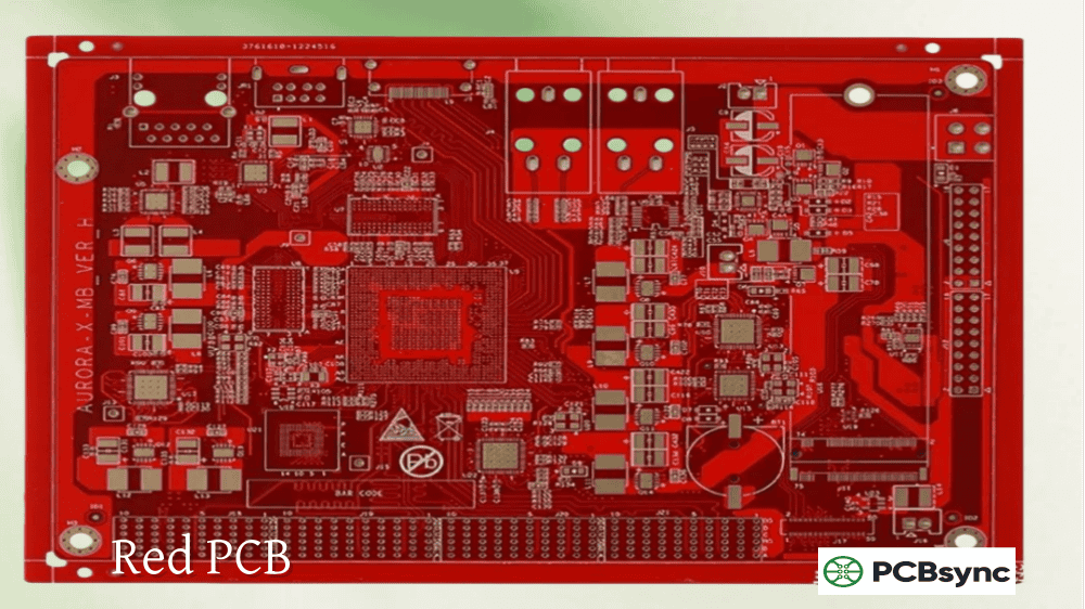
Red PCB Applications
Use Case
Rationale
Prototype identification
Visual distinction from production
Gaming hardware
Aesthetic appeal
Brand differentiation
Marketing purposes
Revision tracking
Color-code different versions
Red provides good contrast and bold appearance but requires magnification for fine-trace inspection.
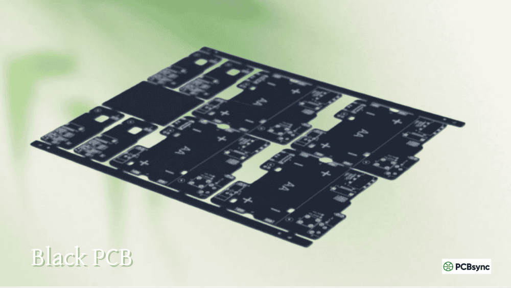
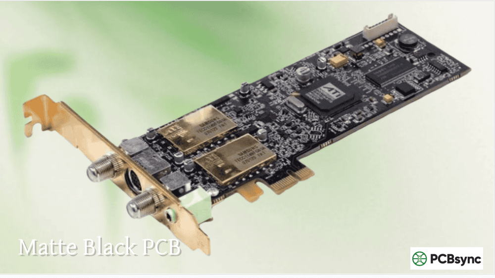
Black PCB Applications
Use Case
Rationale
Consumer electronics (Apple-style)
Premium appearance
LED applications
Reduces light reflection
Optical equipment
Minimizes stray light
Luxury products
High-end aesthetic
Black has the highest defect rate during manufacturing and lowest trace visibility. Use only when appearance justifies the tradeoffs.
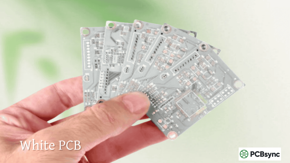
White PCB Applications
Use Case
Rationale
LED lighting
Maximum light reflection
Photographic equipment
Neutral background
Medical devices
Clean appearance
High-brightness applications
Enhanced reflectivity
White shows contamination easily and can yellow with heat exposure during rework.
Modern green PCB solder masks are formulated to meet environmental and safety standards that matter for many applications.
RoHS and Environmental Compliance
Factor
Green Solder Mask Status
RoHS compliance
Standard for all major suppliers
Lead-free compatible
Yes
Halogen-free options
Available
VOC emissions
Low in cured state
Recyclability
Standard e-waste processing
Green solder masks do not typically contain heavy metals like cobalt or carbon that appear in some colored formulations. This makes green a safer choice for applications where material composition matters, such as medical devices or products sold in regions with strict environmental regulations.
Thermal Performance
Property
Green Performance
Heat absorption
Moderate (less than black)
Thermal stability
Excellent
Discoloration resistance
Good
Rework tolerance
Multiple cycles
Black solder masks absorb more heat, which can cause thermal management issues in high-power applications. Green provides a good balance—it doesn’t absorb excessive heat like black but isn’t as reflective as white, which can cause glare issues during inspection.
Manufacturing Process Considerations
Understanding how green PCB solder mask is applied helps explain its advantages.
Solder Mask Application Methods
Method
Description
Green Optimization
LPI (Liquid Photo-Imageable)
Most common, UV cured
Fully optimized
DFSM (Dry Film)
Sheet application
Well established
Screen printing
Traditional method
Original process
LPI solder mask, the dominant modern process, has been refined primarily with green formulations. The UV curing process works most consistently with green pigments, which absorb UV light effectively at the wavelengths used in production equipment.
Following these practices ensures you get the most from your green PCB manufacturing experience.
Solder Mask Layer Best Practices
Practice
Benefit
Define solder mask expansion
Consistent pad exposure
Specify dam width requirements
Prevents solder bridging
Include solder mask on vias
Prevents solder wicking (if desired)
Review Gerber output
Verify mask coverage
Check manufacturer minimums
Ensure design is manufacturable
Documentation Requirements
Element
Include in Fabrication Notes
Solder mask color
“Green LPI solder mask both sides”
Finish type
Matte or gloss preference
Coverage requirements
Tented vias, exposed copper, etc.
IPC class
Class 2 or Class 3 requirements
Silkscreen color
Typically white on green
Common Green PCB Specifications
Parameter
Standard Specification
Solder mask type
LPI (Liquid Photo-Imageable)
Color
Green (RAL 6032 or equivalent)
Finish
Matte or gloss
Silkscreen
White epoxy
Minimum dam
3 mil (0.076 mm)
Thickness
0.5–1.5 mil typical
Frequently Asked Questions About Green PCB
Why are most PCBs green?
Green became the industry standard through a combination of historical factors and genuine technical advantages. Early epoxy-based solder masks naturally cured to green colors, military specifications required green, and manufacturing equipment was optimized for green surfaces. The technical benefits—excellent inspection contrast, lowest eye strain, smallest solder mask dams, and optimal AOI performance—reinforced this choice. Today, green remains dominant because it offers the best combination of cost, quality, and manufacturability.
Does green PCB perform better electrically than other colors?
The solder mask color itself has minimal direct impact on electrical performance. The solder mask’s primary functions—protecting traces from oxidation, preventing solder bridges, and providing insulation—work the same regardless of color. However, green indirectly supports better electrical performance through superior manufacturing quality control. Better inspection means fewer defects reach customers, and the optimized green process produces more consistent results.
When should I choose a color other than green for my PCB?
Consider alternatives when aesthetics matter for your application (consumer products, gaming hardware), when you need to visually distinguish board revisions or prototypes, or when specific optical properties are required (white for LED reflection, black for light absorption). If your product will be visible to end users and appearance affects perceived quality or brand identity, alternative colors may justify their higher cost and longer lead times.
How much more does a non-green PCB cost?
Blue and red typically add 10–20% to solder mask cost compared to green. Black and white can add 15–25% or more. Custom colors may increase costs by 20–50% and extend lead times by one to two weeks. For prototype quantities, the absolute dollar difference is small. For production volumes, the percentage difference becomes significant. Most online PCB services offer green, blue, red, black, and white at standard or slightly premium pricing.
Can I get green PCB in different shades?
Yes, green solder mask comes in various shades including signal green, mint green, and darker olive tones. The specific shade depends on the fabricator’s material supplier and may vary slightly between orders. If precise color matching matters for your application, request samples or specify a RAL color code. Most fabricators offer matte and gloss finishes in green, which affects appearance more than the specific shade.
Choosing the Right PCB Color for Your Project
For the vast majority of applications, green PCB remains the optimal choice. The combination of lowest cost, fastest delivery, best inspection capability, finest feature resolution, and decades of process optimization makes green the default recommendation for production boards, prototypes, and everything in between.
Choose alternative colors when you have specific reasons: brand requirements, visual product differentiation, optical performance needs, or aesthetic preferences that justify the tradeoffs. When you do choose an alternative, select a fabricator experienced with that color and allow extra time for potential manufacturing adjustments.
The green circuit board earned its place as the industry standard through practical performance, not tradition alone. Understanding why green works so well helps you make informed decisions about when to stick with the standard and when alternatives genuinely serve your project better.
Inquire: Call 0086-755-23203480, or reach out via the form below/your sales contact to discuss our design, manufacturing, and assembly capabilities.
Quote: Email your PCB files to Sales@pcbsync.com (Preferred for large files) or submit online. We will contact you promptly. Please ensure your email is correct.
Notes: For PCB fabrication, we require PCB design file in Gerber RS-274X format (most preferred), *.PCB/DDB (Protel, inform your program version) format or *.BRD (Eagle) format. For PCB assembly, we require PCB design file in above mentioned format, drilling file and BOM. Click to download BOM template To avoid file missing, please include all files into one folder and compress it into .zip or .rar format.


