Inquire: Call 0086-755-23203480, or reach out via the form below/your sales contact to discuss our design, manufacturing, and assembly capabilities.
Quote: Email your PCB files to Sales@pcbsync.com (Preferred for large files) or submit online. We will contact you promptly. Please ensure your email is correct.
Notes: For PCB fabrication, we require PCB design file in Gerber RS-274X format (most preferred), *.PCB/DDB (Protel, inform your program version) format or *.BRD (Eagle) format. For PCB assembly, we require PCB design file in above mentioned format, drilling file and BOM. Click to download BOM template To avoid file missing, please include all files into one folder and compress it into .zip or .rar format.
Having spent fifteen years in PCB assembly, I can tell you that soldering flex PCB is where many experienced technicians struggle. The skills that work perfectly on rigid FR-4 boards can lead to disaster on flexible circuits. I’ve seen lifted pads, delaminated substrates, and cracked solder joints on flex assemblies from technicians who solder rigid boards flawlessly every day.
The fundamental issue is that flexible circuits aren’t just thin rigid boards. The polyimide substrate, the adhesive systems, and the thin copper traces all behave differently under heat. Master these differences, and you’ll produce reliable flex assemblies. Ignore them, and you’ll generate expensive scrap.
This guide covers everything you need to know about soldering flex PCB successfully, from material preparation through inspection and rework.
Understanding Flex PCB Construction and Its Impact on Soldering
Before touching a soldering iron to a flex circuit, you need to understand what makes these boards different from their rigid counterparts.
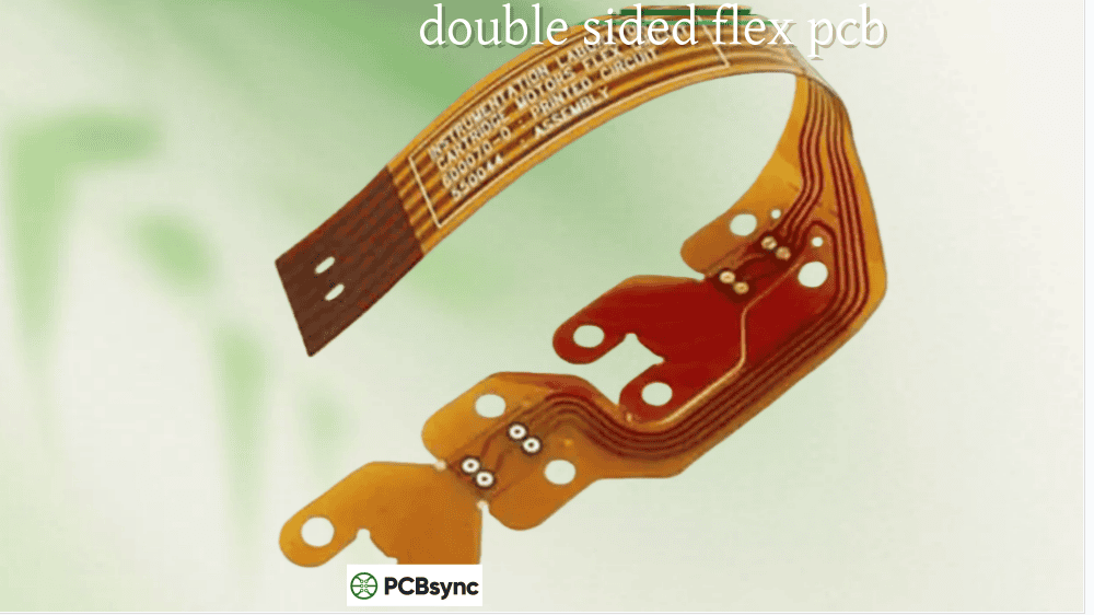
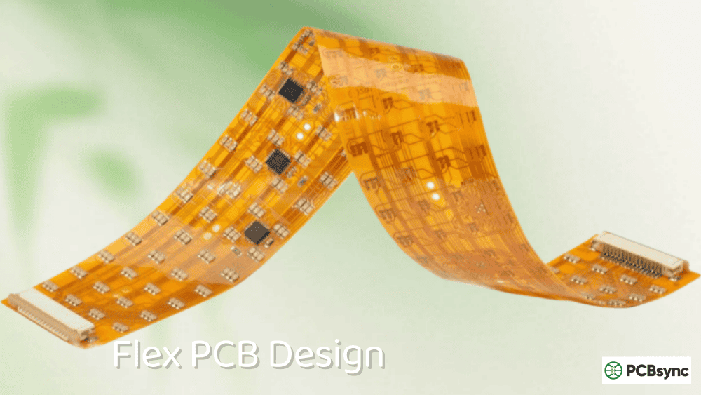
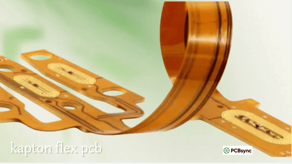
A flexible printed circuit board uses a polyimide film (typically Kapton or similar material) as its base substrate instead of the fiberglass-reinforced epoxy found in FR-4 boards. This polyimide film is laminated to thin copper foil using either adhesive bonding or adhesiveless direct casting. A coverlay (polyimide plus adhesive) protects the copper traces, leaving only the solder pads exposed.
Why Traditional Soldering Approaches Fail on Flex
The adhesive system in flex circuits is fundamentally different from rigid boards. Where FR-4 uses a cohesive epoxy that tolerates high temperatures, flex adhesives are designed to remain pliable. When you apply soldering iron heat to a flex circuit, this adhesive can soften, allowing copper pads to lift from the substrate.
Additionally, polyimide absorbs moisture from the atmosphere. If you solder a flex circuit that hasn’t been properly dried, that moisture turns to steam at soldering temperatures. The result is delamination and blistering that can destroy the circuit in seconds.
The thin copper traces (often 0.5 oz or 1 oz compared to 1-2 oz on rigid boards) also heat faster and are more susceptible to damage from excessive temperature or dwell time.
Essential Pre-Soldering Preparation for Flex PCB
Proper preparation separates successful flex assembly from a pile of scrap material. Never skip these steps.
Pre-Baking Flex Circuits Before Assembly
The single most important preparation step is pre-baking to remove absorbed moisture. Polyimide can absorb up to 3% of its weight in water under humid conditions. That moisture will cause violent delamination when it vaporizes during soldering.
Circuit Type
Baking Temperature
Minimum Duration
Single/Double-Sided Flex
105-115°C (221-239°F)
2-3 hours
3-Layer Polyimide
105-115°C (221-239°F)
3-4 hours
4+ Layer Flex
105-115°C (221-239°F)
4+ hours
Rigid-Flex (≤1.0mm)
105-115°C (221-239°F)
2 hours
Rigid-Flex (1.0-2.0mm)
105-115°C (221-239°F)
4 hours
Rigid-Flex (2.0-4.0mm)
105-115°C (221-239°F)
6 hours
After baking, you have a limited window to complete soldering. Polyimide reabsorbs moisture quickly, so plan to solder within 30 minutes to 8 hours after baking, depending on ambient humidity. Store pre-baked boards in sealed bags with desiccant if immediate soldering isn’t possible.
Cleaning and Surface Preparation
Clean the flex circuit with isopropyl alcohol (90% or higher concentration) to remove oils, dust, and contamination. Any residue on solder pads will interfere with wetting and joint formation.
Apply flux to solder pads using a flux pen or brush before soldering. Flex circuits often require more flux than rigid boards because the thermal properties of polyimide demand faster heat transfer. Use a no-clean flux formulated for flex circuit applications. These fluxes are designed to prevent substrate damage and produce minimal residue.
Fixturing and Support Requirements
Unlike rigid boards that maintain their shape on a conveyor or workstation, flex circuits are floppy and prone to movement. Proper fixturing is essential.
For hand soldering, secure the flex circuit to a rigid backing using Kapton tape or temporary adhesive. The backing prevents the circuit from shifting during soldering and provides thermal mass to distribute heat more evenly.
For SMT reflow, flex circuits must be mounted in rigid carrier pallets (jigs) with milled openings that expose the solder areas. This fixturing maintains dimensional accuracy through the entire reflow process, preventing warping and component misalignment.
Temperature control is critical when soldering flex PCB. The fundamental rule is simple: use the lowest effective temperature that produces acceptable joints.
Recommended Temperature Settings by Method
Soldering Method
Temperature Range
Notes
Hand Soldering (Lead-Free)
260-290°C (500-554°F)
Use temperature-controlled station
Hand Soldering (Leaded)
260-280°C (500-536°F)
Lower end preferred
Hot Air Rework
343-371°C (650-700°F)
Avoid excessive airflow
Reflow Peak (Lead-Free SAC305)
235-245°C (455-473°F)
TAL: 60-90 seconds
Reflow Peak (SnPb)
210-220°C (410-428°F)
When leaded solder permitted
Hot Bar Soldering
200-400°C (392-752°F)
Application dependent
Preheating
80-150°C (176-302°F)
Below Tg of coverlay adhesive
The coverlay adhesive in flex circuits typically has a glass transition temperature (Tg) lower than polyimide itself. Exceeding this temperature for extended periods will cause the coverlay to separate from the base material. This is why controlled heating profiles matter more on flex than rigid boards.
Reflow Profile Considerations for Flex PCB
When using reflow soldering for flex PCB assembly, the thermal profile requires careful adjustment from standard rigid board parameters.
Preheat Zone: Ramp gradually at 1-2°C per second to reach 150-180°C. Rapid heating causes thermal shock that stresses the adhesive bonds. Hold in the soak zone for 60-120 seconds to activate flux and equalize temperature across the assembly.
Reflow Zone: The peak temperature for lead-free solder should reach 235-245°C, but time above liquidus (TAL) must be carefully controlled. Target 60-90 seconds maximum above liquidus. Longer exposure degrades the polyimide substrate and adhesives.
Cooling Zone: Cool at a controlled rate of 2-4°C per second. Faster cooling induces thermal stress that can crack solder joints. Allow joints to solidify naturally without mechanical disturbance.
Hand Soldering Techniques for Flex PCB
Hand soldering flex PCB requires modified techniques compared to rigid board work. The key differences involve dwell time, pressure, and thermal management.
Step-by-Step Hand Soldering Process
Secure the circuit: Tape the flex PCB to a rigid backing with Kapton tape, leaving solder areas accessible. The backing prevents movement and provides thermal stability.
Pre-tin pads if necessary: For difficult joints, pre-tinning both the pad and component lead improves wetting and reduces the time the iron must contact the flex material.
Apply flux: Cover each pad with a thin layer of flux using a flux pen. Flux promotes solder flow and reduces the temperature and time needed to form good joints.
Heat the joint, not the flex: Position the soldering iron tip to contact both the pad and component lead simultaneously. Apply solder to the joint, not the iron tip.
Work quickly: Limit contact time to 2-3 seconds per joint. If a joint doesn’t form properly, remove the iron, allow cooling, then retry. Multiple short heating cycles cause less damage than one prolonged exposure.
Avoid pressure: Use the minimum pressure needed to maintain contact. Excessive downward force on the iron can damage pads or push them off the substrate while the adhesive is softened.
Recommended Hand Soldering Equipment
For soldering flex PCB by hand, use a temperature-controlled soldering station with digital display and fast recovery time. Unregulated irons or simple pencil irons run too hot and lack the precision needed for flex work.
Select fine conical or chisel tips in the 0.5mm to 1.5mm range. Larger tips transfer too much heat to surrounding areas. Keep tips clean and freshly tinned for optimal heat transfer.
Use SAC305 (Sn96.5/Ag3/Cu0.5) or similar lead-free solder in 0.015″ to 0.020″ diameter wire. This alloy offers good wetting and flex fatigue resistance. For applications where leaded solder is permitted, 63/37 SnPb provides lower working temperatures.
Advanced Soldering Flex PCB Techniques
Complex flex assemblies often require techniques beyond standard hand soldering or reflow. These advanced methods offer precision and repeatability for challenging applications.
Hot Bar Soldering for Flex-to-PCB Connections
Hot bar soldering (also called thermocompression bonding or pulse heated soldering) is the preferred method for attaching flex circuits to rigid boards. A heated thermode applies simultaneous heat and pressure to create all solder joints at once.
The process works as follows: pre-tinned flex leads are aligned over corresponding pads on the rigid board, the thermode descends and applies controlled pressure, heat is pulsed through the thermode to reflow the solder, then the assembly cools under pressure to solidify joints.
Hot bar soldering advantages for flex PCB include:
Consistent joint quality across all connections
Controlled force prevents pad lifting
Rapid cycle times for production environments
No mechanical stress from individual iron contact
Suitable for fine-pitch connectors and ZIF sockets
Temperature settings typically range from 200-400°C depending on solder alloy and substrate materials. Bonding strength of 0.05-0.09N is typical for properly formed joints.
Laser Soldering for High-Precision Flex Assembly
Laser soldering uses a focused laser beam to deliver heat energy directly to solder joints. This non-contact method offers exceptional precision for sensitive flex circuit applications.
The laser beam can focus to spot sizes as small as 100-300 microns, allowing selective heating without affecting surrounding areas. Temperature control within ±5°C is achievable with advanced systems.
Laser soldering is particularly valuable for flex PCB work because it applies no mechanical force to the substrate. Traditional soldering irons can tear or delaminate thin flex materials. The laser’s non-contact nature eliminates this risk entirely.
Common applications include fine-pitch SMD components (0201, 0402 packages), camera modules, smartphone assemblies, and medical devices where precision is critical.
Common Soldering Flex PCB Challenges and Solutions
Even experienced technicians encounter problems when soldering flex PCB. Understanding these challenges and their solutions prevents costly failures.
Delamination and Blistering
Problem: Layers separate during or after soldering, often appearing as bubbles or raised areas in the coverlay.
Cause: Moisture trapped in the polyimide substrate vaporizes at soldering temperatures, creating internal pressure that forces layers apart.
Solution: Always pre-bake flex circuits before assembly. Implement proper storage in sealed bags with desiccant. Reduce peak temperatures and time above liquidus during reflow.
Lifted Pads
Problem: Copper pads separate from the polyimide substrate during soldering or component removal.
Cause: Excessive heat softens the adhesive bonding copper to polyimide. Combined with mechanical stress from the iron or component, the pad lifts.
Solution: Use minimum effective temperatures, limit dwell time to 2-3 seconds, avoid downward pressure on the iron, and preheat the board to reduce thermal shock.
Cold Solder Joints
Problem: Joints appear dull and grainy with poor fillet formation.
Cause: Insufficient heat to fully melt solder and wet surfaces. Common when operators compensate for flex sensitivity by using temperatures that are too low.
Solution: Use adequate temperature but minimize dwell time. Apply fresh flux to improve wetting. Ensure proper tip-to-joint contact.
Warping and Distortion
Problem: Flex circuit warps or distorts during soldering, causing component misalignment.
Cause: Uneven heating creates thermal stress. The different thermal expansion rates of copper and polyimide cause the circuit to curve.
Solution: Use proper fixturing and carrier pallets. Implement preheating to equalize temperature. Apply even heating across the assembly. Allow controlled cooling without rapid temperature changes.
Cracked Solder Joints
Problem: Joints develop cracks during use, particularly in dynamic flex applications.
Cause: Solder is not flexible. Joints in flex zones experience mechanical stress during bending that fatigues and cracks the solder.
Solution: Design flex circuits with solder joints only in areas that won’t bend during use. Use stiffeners under component mounting areas. Apply conformal coating to reinforce joints. Consider potting compounds for additional mechanical support in high-stress areas.
Inspection and Quality Control for Flex PCB Solder Joints
Thorough inspection catches defects before they cause field failures. Flex PCB assemblies require attention to both solder joint quality and substrate condition.
Visual Inspection Criteria
Examine joints under magnification (10x minimum) for:
Complete wetting with smooth, concave fillets
Absence of solder bridges between adjacent pads
No solder balls or splatter
No signs of overheating (discoloration, charring)
No visible cracks in joints or substrate
No coverlay lifting or blistering
Proper component alignment and orientation
Electrical Testing
Perform continuity testing between connection points to verify all joints are electrically sound. Check for shorts between adjacent traces or pads that might indicate bridging not visible to inspection.
Frequently Asked Questions About Soldering Flex PCB
Can I use a regular soldering iron for flex PCB?
Yes, but only temperature-controlled models set to appropriate temperatures (typically 260-290°C for lead-free solder). Standard unregulated irons often run too hot for flex circuits and lack the precision needed to prevent damage. Invest in a quality soldering station with digital temperature display and use fine tips (0.5-1.5mm) for flex work.
What causes my flex PCB to blister during soldering?
Blistering almost always results from moisture trapped in the polyimide substrate. When the circuit heats to soldering temperatures, this moisture vaporizes and creates pressure between layers. The solution is pre-baking flex circuits at 105-115°C for 2-6 hours (depending on construction) before assembly. Always store baked boards properly and complete soldering within the recommended time window.
How do I prevent lifted pads when soldering flex circuits?
Lifted pads occur when heat softens the adhesive bond while mechanical stress is applied. Prevent this by using minimum effective temperatures, limiting iron contact to 2-3 seconds maximum, avoiding downward pressure on the soldering iron, and preheating the board to reduce thermal shock. If a pad does lift, stop immediately, allow cooling, and evaluate whether the circuit can be salvaged or must be scrapped.
What’s the difference between soldering flex PCB and rigid PCB?
The key differences involve temperature sensitivity, mechanical handling, and preparation requirements. Flex circuits use adhesive systems that soften at lower temperatures than FR-4 epoxy, require pre-baking to remove moisture, need fixturing support because they’re not self-supporting, and have thinner copper traces that heat faster. You cannot use the same temperature profiles or techniques on flex that work for rigid boards.
Can flex PCBs go through reflow soldering multiple times?
Yes, but with limitations. Each reflow cycle degrades the polyimide substrate and adhesives, increasing delamination risk. Most flex materials tolerate 2-3 reflow cycles maximum. If rework requires additional thermal exposure, re-bake the circuit first to remove any reabsorbed moisture. For high-reliability applications, limit reflow passes and perform rigorous inspection after each cycle.
Mastering Soldering Flex PCB: Final Thoughts
Successful soldering flex PCB requires respecting the fundamental differences between flexible and rigid circuit materials. The polyimide substrate, adhesive systems, and thin copper traces demand modified approaches to temperature, time, and mechanical handling.
Start with proper preparation: pre-bake to remove moisture, clean surfaces thoroughly, apply appropriate flux, and secure the circuit in proper fixtures. Use the lowest effective temperatures with minimal dwell times. Inspect carefully for both joint quality and substrate damage.
With practice and attention to these principles, you’ll produce flex PCB assemblies that deliver the reliability these circuits are designed to provide. The extra care required pays dividends in reduced scrap, fewer field failures, and satisfied customers.
This guide reflects practical manufacturing experience with flex circuit assembly. Always verify specific parameters with your material suppliers and adjust processes based on your equipment and application requirements.
Inquire: Call 0086-755-23203480, or reach out via the form below/your sales contact to discuss our design, manufacturing, and assembly capabilities.
Quote: Email your PCB files to Sales@pcbsync.com (Preferred for large files) or submit online. We will contact you promptly. Please ensure your email is correct.
Notes: For PCB fabrication, we require PCB design file in Gerber RS-274X format (most preferred), *.PCB/DDB (Protel, inform your program version) format or *.BRD (Eagle) format. For PCB assembly, we require PCB design file in above mentioned format, drilling file and BOM. Click to download BOM template To avoid file missing, please include all files into one folder and compress it into .zip or .rar format.


