Inquire: Call 0086-755-23203480, or reach out via the form below/your sales contact to discuss our design, manufacturing, and assembly capabilities.
Quote: Email your PCB files to Sales@pcbsync.com (Preferred for large files) or submit online. We will contact you promptly. Please ensure your email is correct.
Notes: For PCB fabrication, we require PCB design file in Gerber RS-274X format (most preferred), *.PCB/DDB (Protel, inform your program version) format or *.BRD (Eagle) format. For PCB assembly, we require PCB design file in above mentioned format, drilling file and BOM. Click to download BOM template To avoid file missing, please include all files into one folder and compress it into .zip or .rar format.
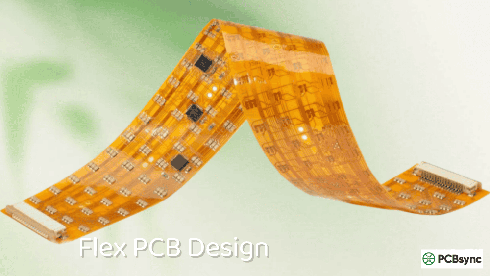
The first time I designed a flex circuit without considering stiffeners, I learned an expensive lesson. The board flexed exactly where it shouldn’t—right at the connector pads—and the solder joints cracked during the first assembly attempt. Twenty prototype boards, all useless. That experience taught me that PCB stiffener selection isn’t optional when designing flexible circuits; it’s fundamental to the design succeeding.
If you’re working with flex or rigid-flex PCBs, understanding when and how to use stiffeners will save you from similar failures. This guide covers the types of PCB stiffeners available, the materials used, and specifically when your design requires them.
A PCB stiffener is a rigid material layer attached to specific areas of a flexible printed circuit board to provide mechanical support. Unlike the functional layers of your PCB, a stiffener isn’t part of the electrical circuit—it exists purely to add rigidity where needed.
The purpose is straightforward: flex circuits are thin and bendable by design, but certain areas require stability. Component mounting locations, connector interfaces, and areas subject to repeated handling all benefit from localized rigidity. Without stiffeners, these areas would flex during assembly or operation, potentially cracking solder joints, damaging components, or causing the circuit to fail.
PCB stiffeners are typically attached during final fabrication steps, after the flex circuit layers are complete. They can be bonded using thermal adhesives under heat and pressure, or attached with pressure-sensitive adhesives (PSA) depending on application requirements.
Why Flex Circuits Need PCB Stiffeners
Flexible PCBs excel at bending, folding, and fitting into tight spaces, but that flexibility becomes a liability in certain situations. Here’s when a PCB stiffener becomes essential:
Component Support and Solder Joint Protection
When surface-mount components are placed on flex material, the underlying substrate can bend during pick-and-place assembly or reflow soldering. This bending stresses solder joints before they’re even complete. A stiffener under the component area provides a flat, stable surface that ensures reliable solder connections.
After assembly, components on unsupported flex material can experience stress during handling, installation, or operation. Particularly with heavier components like large connectors, USB ports, or power modules, the flex material simply can’t support the weight without deforming. Stiffeners prevent this deformation and protect solder joint integrity throughout the product’s life.
Connector Interface Requirements
Most connectors—especially zero insertion force (ZIF) connectors—require specific board thicknesses at the interface. A bare flex circuit is typically 0.1-0.3mm thick, far thinner than connector specifications require. PCB stiffeners increase local thickness to match connector requirements, ensuring reliable electrical contact and mechanical retention.
ZIF connectors are particularly demanding, specifying tight tolerances for both thickness (typically 0.2mm or 0.3mm) and dimensional accuracy at the contact fingers. Polyimide stiffeners are the standard solution for ZIF applications because they can be precisely profiled to meet these specifications.
Controlled Bend Locations
In many applications, you need the flex circuit to bend in specific locations while remaining rigid elsewhere. Stiffeners define these rigid zones, forcing all bending to occur in the designated flex areas. This control prevents random bending that could damage traces or components.
Assembly Handling
Thin flex circuits are difficult to handle during automated assembly. They droop, curl, and don’t feed reliably through pick-and-place equipment. Adding stiffeners—often as a frame around the circuit perimeter—allows flex circuits to run through standard SMT assembly lines like rigid boards, eliminating the need for specialized fixtures or carriers.
Types of PCB Stiffener Materials
Different applications call for different stiffener materials. The four primary options each serve specific purposes:
FR4 Stiffeners
FR4—the same glass-reinforced epoxy used for rigid PCBs—is the most common PCB stiffener material. It’s cost-effective, readily available, and provides excellent mechanical support for component mounting areas.
Advantages of FR4 Stiffeners:
Uses the same material as standard PCBs, simplifying supply chain
Provides solid, flat support during SMT assembly
Allows direct plated through-hole (PTH) component attachment
Cost-effective compared to specialty materials
Easy to drill for access holes and mounting features
FR4 stiffener thickness ranges from 0.010″ (0.25mm) to 0.059″ (1.5mm), with 0.020″, 0.031″, and 0.039″ being the most common. The general rule is to use the thickest stiffener your design allows—up to 0.059″ replicates traditional rigid PCB thickness.
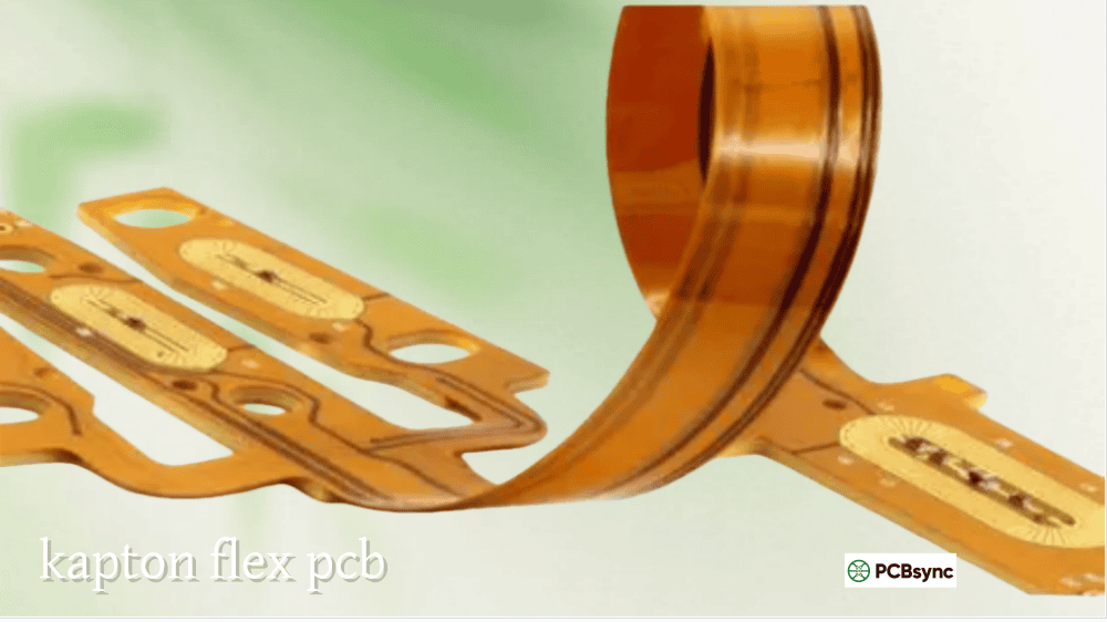
Polyimide (PI) Stiffeners
Polyimide stiffeners are made from the same high-temperature polymer used in flex circuit substrates. Kapton is the most recognized brand name for polyimide film used in stiffeners.
Advantages of Polyimide Stiffeners:
Essential for meeting ZIF connector thickness specifications
Can be precisely profiled for tight dimensional tolerances
Provides solder resistance and high bond strength
Thinner than FR4 options (0.001″ to 0.010″)
Matches flex material thermal expansion characteristics
Polyimide is the only viable option for ZIF connector applications because it allows both the circuit outline and stiffener to be profiled simultaneously, meeting the tight tolerances ZIF connectors require.
Stainless Steel Stiffeners
When heat dissipation is a primary concern, stainless steel stiffeners provide both mechanical support and thermal management. The metal conducts heat away from components more effectively than FR4 or polyimide.
Advantages of Stainless Steel Stiffeners:
Excellent heat dissipation properties
Very thin profiles possible (0.1-0.45mm)
High strength-to-thickness ratio
Suitable for space-constrained designs requiring rigidity
Stainless steel costs significantly more than FR4 or polyimide and requires specialized attachment methods, but for applications combining thermal and mechanical requirements in minimal space, it’s often the best choice.
Aluminum Stiffeners
Aluminum offers the best thermal conductivity of common stiffener materials, making it ideal when heat dissipation is the primary concern.
Advantages of Aluminum Stiffeners:
Superior thermal conductivity
Lighter than stainless steel
Can serve as heat sink when properly attached
Good EMI shielding properties
Like stainless steel, aluminum stiffeners carry a cost premium and require specific adhesive systems or mechanical attachment methods.
Two primary methods exist for attaching stiffeners to flex circuits. The choice depends on your application requirements, reliability needs, and cost constraints.
Thermal Bonding (Heat and Pressure)
Thermal bonding uses the same adhesive systems as coverlay attachment—flexible epoxy or acrylic adhesives cured under heat and pressure in a lamination press. This method creates a permanent, high-strength bond.
Thermal Bonding Characteristics:
Strongest bond strength available
Permanent attachment—cannot be reworked
Cost-effective for production volumes
Requires lamination press equipment
Stiffener must extend to circuit outline in most cases
Thermal bonding is the preferred method for high-reliability applications including aerospace, military, and medical devices where bond strength and durability are critical.
Pressure-Sensitive Adhesive (PSA)
PSA attachment uses double-sided adhesive tape (such as 3M467 or 3M9077) to bond the stiffener to the flex circuit. Application is simpler—essentially applying a sticker—but bond strength is lower than thermal bonding.
PSA Characteristics:
Simpler application, no special equipment needed
Can attach stiffeners anywhere on the circuit (not just edges)
Lower bond strength than thermal bonding
Allows rework in some cases
Some PSA types not rated for reflow temperatures
PSA is appropriate for consumer electronics, prototypes, and applications where thermal bonding isn’t feasible due to design constraints.
When You Need a PCB Stiffener: Specific Applications
SMT Component Areas
Any area with surface-mount components benefits from stiffeners. The flat, rigid surface ensures reliable pick-and-place positioning and consistent solder joint formation during reflow.
Design Tip: Extend the stiffener at least 0.030″ (0.75mm) beyond the component footprint boundaries to provide adequate support and reduce stress concentration at stiffener edges.
ZIF Connector Interfaces
ZIF connectors require specific thickness at the contact finger area—typically 0.2mm or 0.3mm total thickness. Polyimide stiffeners are essential here, precisely sized to achieve the required dimensions within connector tolerances.
Design Tip: Always include the ZIF connector manufacturer and part number in your documentation so fabricators can verify thickness requirements.
Plated Through-Hole (PTH) Component Areas
When PTH components mount on flex circuits, the stiffener must be on the same side as component insertion to allow access to solder pads. Clearance holes in the stiffener must be oversized by 0.016″ (0.4mm) relative to PTH holes to accommodate registration tolerances.
Assembly Array Frames
For automated assembly, FR4 stiffeners around the flex circuit perimeter create a rigid frame. This allows the flex assembly to run through standard SMT equipment without special carriers or fixtures.
Bend Transition Areas
Where flex zones meet component areas, stiffeners define the transition and increase the bend radius. This reduces stress on copper traces at the flex-to-rigid boundary, improving reliability during repeated bending.
PCB Stiffener Design Guidelines
Following these design rules will help ensure your stiffeners function properly and your flex circuits are manufacturable:
Overlap Requirements
Stiffener edges should overlap coverlay termination by minimum 0.030″ (0.75mm). This overlap distributes stress across the transition zone rather than concentrating it at a single point.
Thickness Consistency
Use the same stiffener thickness throughout a design when possible. Multiple thicknesses require additional fabrication steps, increasing cost and lead time.
Standard Thicknesses
Specify standard laminate thicknesses (0.010″, 0.020″, 0.031″, 0.039″, 0.047″, 0.059″) to minimize cost and lead time. Non-standard thicknesses may require special material orders.
Clearance Holes
For PTH designs, clearance holes in stiffeners should be 0.016″ larger diameter than the corresponding plated holes in the flex circuit. This prevents interference due to registration tolerances during bonding.
Documentation
Include complete stiffener specifications in your fabrication documentation:
Material type
Thickness
Attachment method
Layer (top, bottom, or both)
Outline dimensions
Hole locations and sizes
Frequently Asked Questions About PCB Stiffeners
What’s the difference between rigid-flex and rigidized flex?
Rigid-flex PCBs have rigid and flexible sections integrated as part of the circuit structure, with traces running between rigid and flex areas. Rigidized flex is simply a flex circuit with stiffeners attached—the stiffeners provide mechanical support but aren’t part of the electrical design. Rigid-flex is more expensive but provides true rigid board functionality in designated areas.
Can I use stiffeners on both sides of a flex circuit?
Yes, but designs with stiffeners on both top and bottom require array configuration review and typically multiple lamination cycles. This increases cost and lead time. When possible, keep stiffeners on one side only.
How does stiffener choice affect cost?
FR4 stiffeners are least expensive, followed by polyimide. Stainless steel and aluminum carry significant cost premiums due to material cost and specialized attachment requirements. Thermal bonding is typically more cost-effective at production volumes, while PSA is cheaper for prototypes and small quantities.
What stiffener thickness should I use for SMT components?
For SMT component support, use the thickest FR4 stiffener your design allows—typically 0.031″ to 0.059″. Thicker stiffeners provide better support and more closely replicate traditional rigid PCB handling characteristics. For ZIF connectors, thickness is determined by connector specifications, not designer preference.
Can stiffeners be added after assembly?
PSA-attached stiffeners can sometimes be added post-assembly, but this isn’t recommended practice. Thermally bonded stiffeners must be attached during fabrication. For best results, design stiffeners into your flex circuit from the start rather than adding them as an afterthought.
Useful Resources for PCB Stiffener Design
Design Standards
IPC-2223: Sectional Design Standard for Flexible Printed Boards
IPC-6013: Qualification and Performance Specification for Flexible Printed Boards
Making Your Decision: Selecting the Right PCB Stiffener
The key questions when selecting stiffeners are:
What function does the stiffener serve?
Component support → FR4 (most cost-effective)
ZIF connector interface → Polyimide (required for tolerance)
Heat dissipation → Aluminum or stainless steel
Thin profile with rigidity → Stainless steel or thin polyimide
What reliability class is required?
IPC Class 2 (consumer) → PSA attachment acceptable
IPC Class 3 (high reliability) → Thermal bonding recommended
What are your cost and lead time constraints?
Standard FR4 thicknesses minimize both
Metal stiffeners and non-standard thicknesses add cost and time
Don’t treat stiffeners as an afterthought. They’re integral to your flex circuit’s mechanical performance, assembly success, and long-term reliability. Get them right in your initial design, specify them clearly in your documentation, and work with your fabricator early to ensure your choices are manufacturable.
The lesson from my first failed flex design stuck with me: a few dollars saved on stiffener design costs far more when twenty prototype boards end up in the scrap bin.
Inquire: Call 0086-755-23203480, or reach out via the form below/your sales contact to discuss our design, manufacturing, and assembly capabilities.
Quote: Email your PCB files to Sales@pcbsync.com (Preferred for large files) or submit online. We will contact you promptly. Please ensure your email is correct.
Notes: For PCB fabrication, we require PCB design file in Gerber RS-274X format (most preferred), *.PCB/DDB (Protel, inform your program version) format or *.BRD (Eagle) format. For PCB assembly, we require PCB design file in above mentioned format, drilling file and BOM. Click to download BOM template To avoid file missing, please include all files into one folder and compress it into .zip or .rar format.


