Inquire: Call 0086-755-23203480, or reach out via the form below/your sales contact to discuss our design, manufacturing, and assembly capabilities.
Quote: Email your PCB files to Sales@pcbsync.com (Preferred for large files) or submit online. We will contact you promptly. Please ensure your email is correct.
Notes: For PCB fabrication, we require PCB design file in Gerber RS-274X format (most preferred), *.PCB/DDB (Protel, inform your program version) format or *.BRD (Eagle) format. For PCB assembly, we require PCB design file in above mentioned format, drilling file and BOM. Click to download BOM template To avoid file missing, please include all files into one folder and compress it into .zip or .rar format.
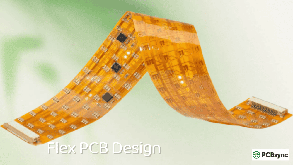
As a PCB engineer who has worked on dozens of flex circuit projects over the past decade, I’ve seen firsthand why Kapton flex PCB has become the industry standard for demanding applications. From aerospace components operating in the vacuum of space to the foldable display in your smartphone, polyimide-based flex circuits are everywhere. In this guide, I’ll break down exactly why DuPont’s Kapton polyimide remains the go-to choice for flex circuit designers and what you need to know when specifying your next project.
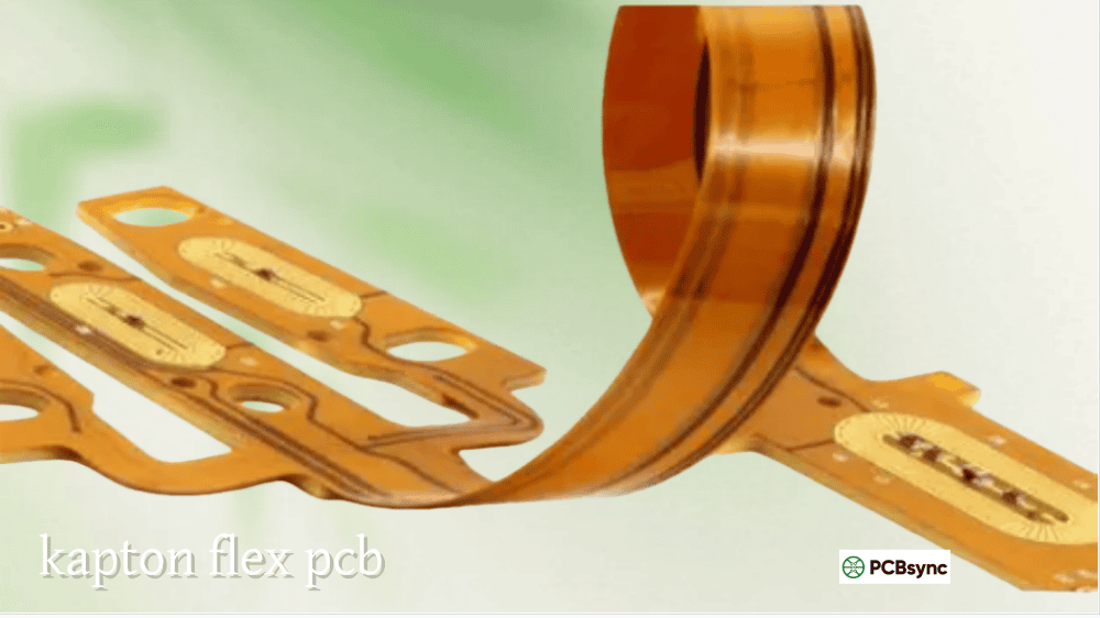
A Kapton flex PCB is a flexible printed circuit board that uses DuPont’s Kapton polyimide film as its base substrate material. Unlike rigid FR-4 boards that snap when bent, a Kapton flexible circuit can twist, fold, and conform to tight spaces while maintaining full electrical functionality.
The construction typically includes these layers:
A thin polyimide base film (12.5µm to 125µm)
Rolled annealed copper foil laminated to the substrate
A Kapton coverlay for circuit protection
Optional stiffeners for component mounting areas
What makes Kapton special isn’t just flexibility. The material maintains its electrical and mechanical properties across extreme temperature ranges, from cryogenic conditions at -269°C to continuous operation above 260°C. I’ve designed circuits for satellite thermal insulation systems where no other material could survive.
Understanding Polyimide: The Chemistry Behind Kapton
Polyimide (PI) is a high-performance polymer synthesized from dianhydride and diamine monomers under condensed conditions. The resulting molecular structure features imide linkages (-CO-N-CO-) that give the material exceptional thermal stability.
DuPont introduced Kapton polyimide films in the 1960s, originally targeting aerospace and defense applications. The material gained public recognition when NASA used it for thermal insulation on the Apollo Lunar Module. That legacy continues today with the International Space Station still relying on Kapton for thermal management.
Key Polyimide Characteristics
The reason polyimide dominates flex circuit applications comes down to its unique combination of properties that no other flexible substrate can match:
Thermal Performance: Kapton’s glass transition temperature exceeds 300°C, allowing continuous operation up to 260°C. Compare this to PET substrates that fail above 150°C.
Mechanical Strength: With a tensile strength of 231 MPa, polyimide is over three times stronger than FR-4 (approximately 70 MPa).
Electrical Properties: A stable dielectric constant of 3.4 and low dissipation factor (0.004-0.007) make Kapton suitable for high-frequency applications.
Why Polyimide is the Preferred Material for Flex Circuits
After evaluating hundreds of flex circuit designs, I can tell you that material selection often determines project success or failure. Here’s why experienced engineers consistently specify Kapton flex PCB substrates over alternatives.
Exceptional Thermal Stability
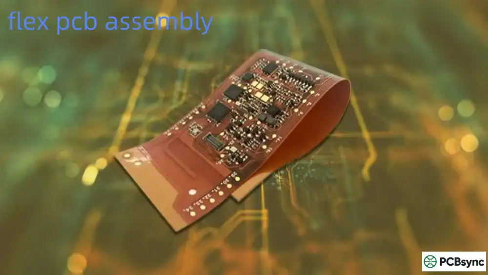
Manufacturing processes like reflow soldering expose circuits to thermal stress that cheaper materials simply cannot handle. Polyimide maintains dimensional stability through lead-free soldering profiles with peak temperatures of 260°C. I’ve seen PET-based flex circuits warp and deform during assembly, leading to component placement failures and scrap.
For applications in engine compartments, industrial furnaces, or aerospace systems, polyimide’s thermal performance is non-negotiable. The material withstands thermal cycling between extreme temperatures without cracking or delamination.
Superior Flex Life and Dynamic Bending
When your design requires dynamic flexing during operation, polyimide is the only practical choice. Kapton flex PCB substrates can withstand over 500 million flex cycles when properly designed. This makes them essential for:
Wearable electronics that bend with body movement
Print heads that cycle thousands of times per minute
Automotive door hinges with daily open/close cycles
Medical devices with articulating components
PET and PEN substrates typically fail after significantly fewer cycles, making them suitable only for static “bend-to-install” applications.
Chemical and Environmental Resistance
Polyimide resists degradation from most organic solvents, acids, oils, and fuels. In automotive under-hood applications, circuits face exposure to transmission fluid, coolant, and fuel vapor. Medical devices undergo harsh sterilization cycles. Kapton’s chemical inertness ensures long-term reliability in these demanding environments.
The material also demonstrates excellent radiation resistance, a critical factor for aerospace and medical imaging applications.
Low Outgassing for Space Applications
Spacecraft electronics must use materials with extremely low outgassing characteristics to prevent contamination of optics and sensors. Kapton’s outgassing loss of approximately 0.58% under vacuum meets NASA’s stringent requirements, making it the default choice for space-grade flex circuits.
Kapton Flex PCB Material Properties Comparison
When evaluating flexible substrate materials, this comparison table summarizes the critical specifications that influence material selection:
Not all Kapton materials are identical. DuPont offers several grades optimized for specific applications. Understanding these variants helps you specify the right material for your design.
Kapton HN (General Purpose)
This is the workhorse of the flex circuit industry. Kapton HN offers an excellent balance of thermal, mechanical, and electrical properties across a wide temperature range. It’s my default recommendation for most standard flex applications.
Best for: General flex circuits, cable harnesses, insulation applications
Kapton FPC (Flex Circuit Specific)
DuPont specifically engineered Kapton FPC for flexible circuit manufacturers. It provides superior dimensional stability and adhesion characteristics compared to general-purpose grades. The material meets IPC-4202C requirements for flex circuit applications.
Best for: High-density flex circuits, multilayer flex, rigid-flex constructions
Kapton HPP-ST (High-Performance Plus)
When your application demands enhanced dimensional stability during thermal processing, HPP-ST delivers. This grade exhibits lower shrinkage during lamination and soldering, reducing registration errors in fine-pitch designs.
Best for: Fine-pitch components, HDI flex circuits, precision applications
Second Generation Polyimides (Pure PI)
These additive-free polyimides offer maximum thermal stability for extreme temperature applications. Without flame retardant additives, they maintain performance at the highest operating temperatures.
Best for: Aerospace, defense, extreme temperature environments
Third Generation Polyimides (Flame Retardant)
These formulations include flame retardant additives for enhanced fire safety. While thermal stability is slightly reduced compared to pure grades, they meet strict flammability requirements for consumer and industrial electronics.
Best for: Consumer electronics, industrial controls, applications requiring UL compliance
Kapton Flex PCB vs FR-4: When to Use Each Material
One question I hear frequently from new engineers is when to use flex versus rigid. Here’s a straightforward comparison:
Criteria
Kapton Flex PCB
FR-4 Rigid PCB
Flexibility
Full dynamic flex capability
None (will fracture)
Thermal Range
-269°C to 260°C
-55°C to 130°C
Tensile Strength
231 MPa
70 MPa
Weight
70% lighter
Standard baseline
Assembly Complexity
Higher
Standard
Cost per Square Inch
5-10x higher
Standard baseline
Thermal Conductivity
Good
Moderate
Vibration Resistance
Excellent
Poor
Design Freedom
3D configurations
Planar only
Use Kapton Flex PCB when:
The design requires bending during installation or operation
Space and weight constraints demand a thin, light solution
The operating environment includes temperature extremes
Vibration and shock resistance are critical
3D packaging configurations are required
Use FR-4 when:
The circuit remains flat throughout its lifecycle
Cost is the primary driver
Standard operating temperatures apply
High layer counts are needed at lower cost
Kapton Flex PCB Applications Across Industries
The versatility of Kapton flex circuits spans virtually every electronics sector. Here are the primary application areas where polyimide substrates excel.
Aerospace and Defense
Satellites, aircraft avionics, and military systems rely on Kapton flex PCB for mission-critical interconnects. The combination of lightweight construction, radiation resistance, and extreme temperature performance makes polyimide irreplaceable in these applications.
Common aerospace uses include:
Thermal insulation blankets
Antenna systems
Engine sensor arrays
Cockpit display interconnects
Consumer Electronics
Every foldable smartphone, laptop hinge, and camera stabilizer depends on flex circuits. The high-density routing capability allows designers to pack more functionality into ever-shrinking device envelopes.
Medical Devices
From implantable pacemakers to diagnostic imaging equipment, medical applications demand reliability and biocompatibility. Polyimide’s inert nature and ability to withstand sterilization processes make it ideal for medical use.
Automotive Electronics
Modern vehicles contain dozens of flex circuits in applications ranging from dashboard displays to engine control modules. Kapton withstands the under-hood thermal environment that destroys lesser materials.
Industrial Equipment
Sensors in chemical plants, furnace controllers, and robotic systems all benefit from polyimide’s chemical resistance and thermal stability.
Design Guidelines for Kapton Flex PCB
Successful flex circuit design requires understanding the unique considerations that differentiate flex from rigid boards.
Bend Radius Considerations
The minimum bend radius depends on circuit construction and whether bending is dynamic or static. For dynamic applications, use a bend radius of at least 10 times the total circuit thickness. Static (install-and-forget) applications can go as low as 6 times thickness.
Copper Selection
Rolled annealed (RA) copper is essential for dynamic flex applications. Its grain structure allows repeated bending without fatigue failure. Electrodeposited (ED) copper costs less but suits only static applications.
Trace Routing in Bend Areas
Route traces perpendicular to the bend axis when possible. Avoid vias, pads, and plated through-holes in flex zones. Use gradual curves rather than right angles, with a minimum radius of 0.75mm to prevent stress concentration.
Stiffener Application
Add FR-4 or polyimide stiffeners in component mounting areas to support SMD devices and connectors during assembly and use.
IDES Prospector Plastics Database for material comparisons
UL iQ for certified material properties and flammability ratings
Frequently Asked Questions About Kapton Flex PCB
What temperature can Kapton flex PCB withstand?
Kapton flex PCB substrates operate continuously at temperatures from -269°C (cryogenic) to 260°C, with short-term exposure capability up to 400°C. This makes them suitable for everything from satellite cryogenics to engine compartment electronics. The glass transition temperature exceeds 300°C, ensuring dimensional stability during lead-free soldering processes with peak temperatures around 260°C.
How many bend cycles can a Kapton flex PCB survive?
A properly designed Kapton flex PCB can withstand over 500 million flex cycles in dynamic applications. Achieving this longevity requires following design guidelines: using rolled annealed copper, maintaining appropriate bend radii (10x circuit thickness minimum for dynamic flex), routing traces perpendicular to the bend axis, and avoiding vias in flex zones.
Is Kapton the same as polyimide?
Kapton is DuPont’s trade name for their specific polyimide film products. While all Kapton is polyimide, not all polyimide is Kapton. Other manufacturers produce polyimide films under different brand names (such as Upilex from UBE Industries). In practice, “Kapton” has become somewhat generic in the industry, similar to how “Kleenex” refers to tissues. When specifying materials, clarify whether you need genuine DuPont Kapton or if equivalent polyimide materials are acceptable.
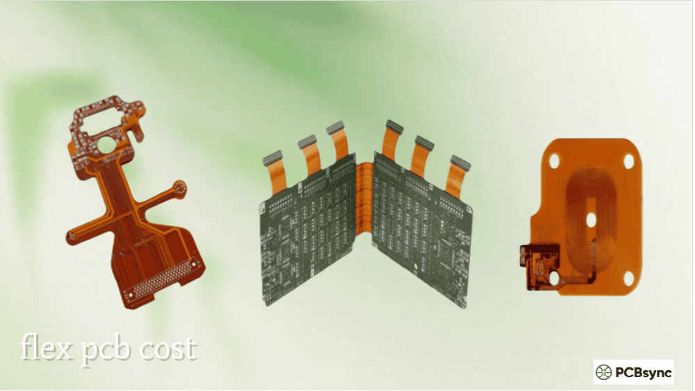
Why is Kapton flex PCB more expensive than FR-4?
Several factors contribute to the higher cost of Kapton flex PCB: raw polyimide material costs more than FR-4 laminate; manufacturing requires specialized equipment and processes; assembly complexity is higher due to the flexible substrate; and lower production volumes mean less economy of scale. Expect flex circuits to cost 5-10 times more than equivalent rigid boards. However, when you factor in the elimination of connectors, cables, and assembly labor that flex circuits enable, total system cost often decreases.
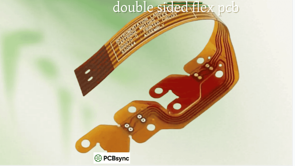
Can components be mounted on both sides of a Kapton flex PCB?
Yes, components can be surface-mounted to both sides of a Kapton flex PCB. This allows higher circuit density, which is particularly valuable in space-constrained applications. Design considerations include ensuring adequate clearance between opposing components during flexing and potentially adding stiffeners to support heavier components. 3D modeling of the assembled circuit helps validate mechanical clearances before production.
Final Thoughts on Kapton Flex PCB Selection
After years of designing flex circuits across industries, my recommendation is straightforward: when reliability matters, specify Kapton polyimide. The higher material cost is insurance against field failures, warranty claims, and product recalls that far exceed any upfront savings from cheaper substrates.
For cost-sensitive consumer products with mild operating conditions, PET or PEN substrates may suffice. But for automotive, aerospace, medical, industrial, or any application where failure isn’t an option, Kapton flex PCB remains the only responsible choice.
Start your next flex circuit design by consulting with your fabricator early. Material selection, layer count, and bend requirements all interact in ways that benefit from manufacturing input during the design phase. The upfront collaboration saves redesign cycles and accelerates your path to production.
This article represents practical engineering experience with flexible circuit design. Always verify material specifications with manufacturer datasheets and consult with your PCB fabricator for application-specific recommendations.
Inquire: Call 0086-755-23203480, or reach out via the form below/your sales contact to discuss our design, manufacturing, and assembly capabilities.
Quote: Email your PCB files to Sales@pcbsync.com (Preferred for large files) or submit online. We will contact you promptly. Please ensure your email is correct.
Notes: For PCB fabrication, we require PCB design file in Gerber RS-274X format (most preferred), *.PCB/DDB (Protel, inform your program version) format or *.BRD (Eagle) format. For PCB assembly, we require PCB design file in above mentioned format, drilling file and BOM. Click to download BOM template To avoid file missing, please include all files into one folder and compress it into .zip or .rar format.


